Flexible heat sink

a heat sink and flexible technology, applied in the direction of laminated elements, lighting and heating apparatus, semiconductor/solid-state device details, etc., can solve problems such as electromagnetic interference problems in electronic devices, and achieve the effects of reducing noise transmission, reducing shock and vibration of components and/or the larger surface structure, and reducing the flexibility of the heat sink

Inactive Publication Date: 2008-07-15
3M INNOVATIVE PROPERTIES CO
View PDF103 Cites 48 Cited by
  • Summary
  • Abstract
  • Description
  • Claims
  • Application Information

AI Technical Summary

Benefits of technology

[0010]Another advantage of the present invention is in the flexibility of the heat sink. The base of the heat sink can be flexible, while the polymeric protrusions are also flexible or remain relatively rigid. Thus, the inventive heat sink can be adapted to conform to uneven surfaces of any practical scale from a rough surface to an uneven surface, and even to macroscopic chip dimensions.
[0011]The flexible base of the heat sink also allows the heat sink to be placed onto surfaces that are not perfectly coplanar so a single flexible heat sink article provides heat dissipation to more than one non-coplanar device. The flexibility also can provide a damping benefit that reduces shock and vibration of the components and / or the larger surface structure that the heat sinks are attached directly or indirectly to (i.e., a flexible heat sink provides damping to a chip device to which it is directly attached, and additional damping to the printed circuit board to which this chip having the heat sink is attached). The flexible heat sink also reduces noise transmission in contrast to aluminum heat sinks which can transmit sound much like a tuning fork when attached to a vibrating component.
[0012]The heat sink can be provided in a roll form (for example the flexible heat sink of FIG. 1A is shown in a roll of about 12 cm inner diameter), and then cut to any desired shape such as via die cutting. The heat sink may further comprise a thermal interface material layer, which may be a thermally conductive adhesive layer. The protrusion quantity, placement, size, and base thickness can be varied independently to accommodate uneven temperature regions of a heat source. In addition, webs, rails, fins, foils, sails, and the like, in any combination can be used to direct heat and air flow. The polymeric protrusions can be of constant or varying height(s) and / or shape(s). The polymeric protrusions and base, which may comprise an adhesive, can be made independently or simultaneously through various processes.
[0013]Other features and advantages of the invention will be apparent from the following

Problems solved by technology

The metal heat sinks are normally electrically conductive, and may contribute to electromagnetic interference problems in electronic devices.

Method used


Image

  • Flexible heat sink
  • Flexible heat sink
  • Flexible heat sink

Examples


example 1

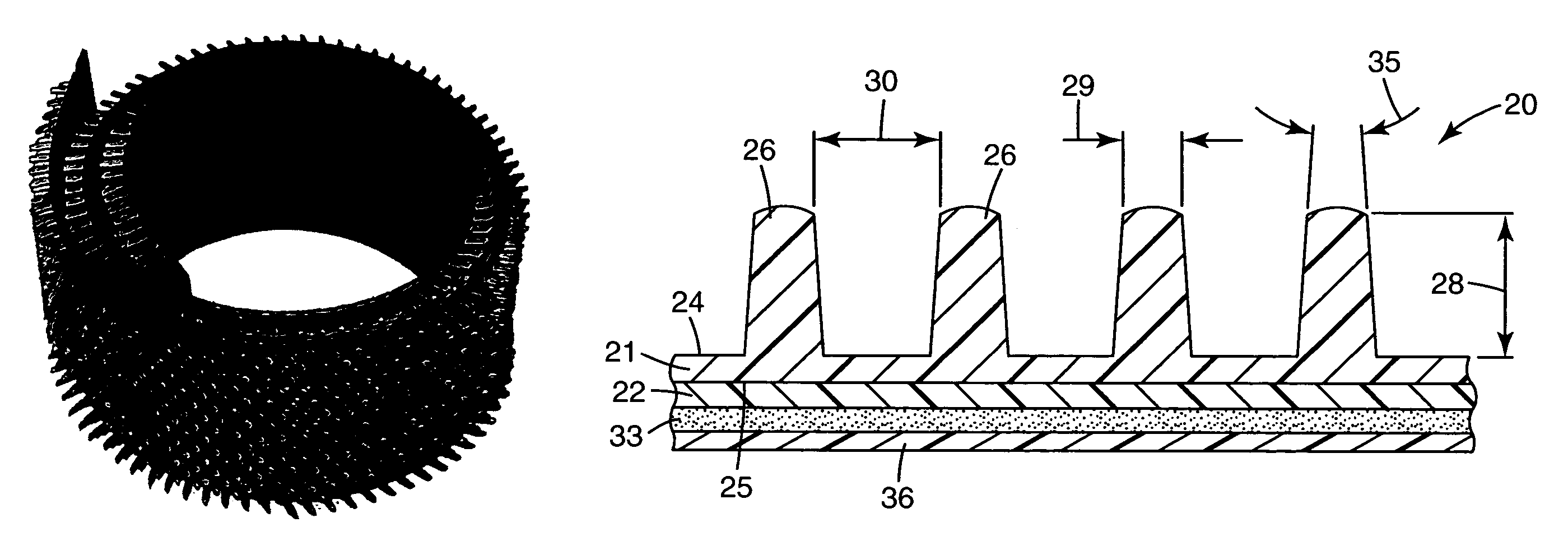
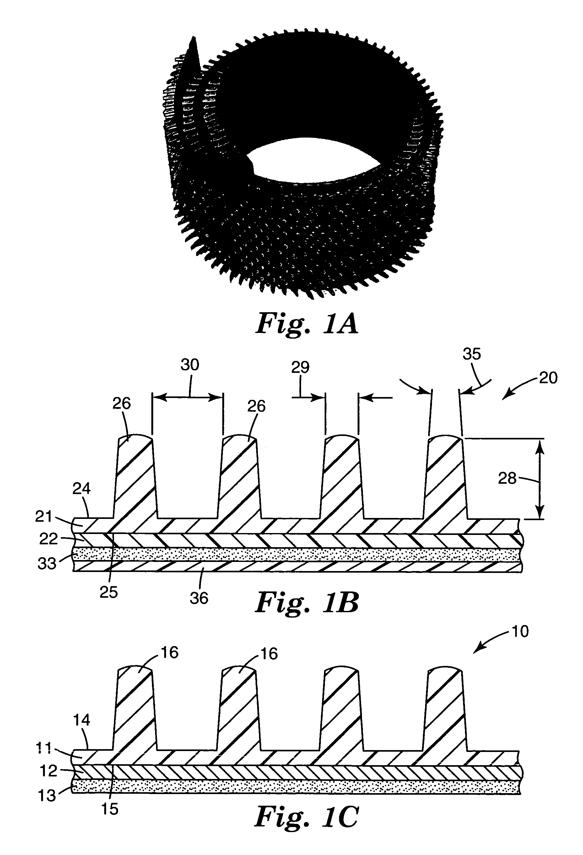
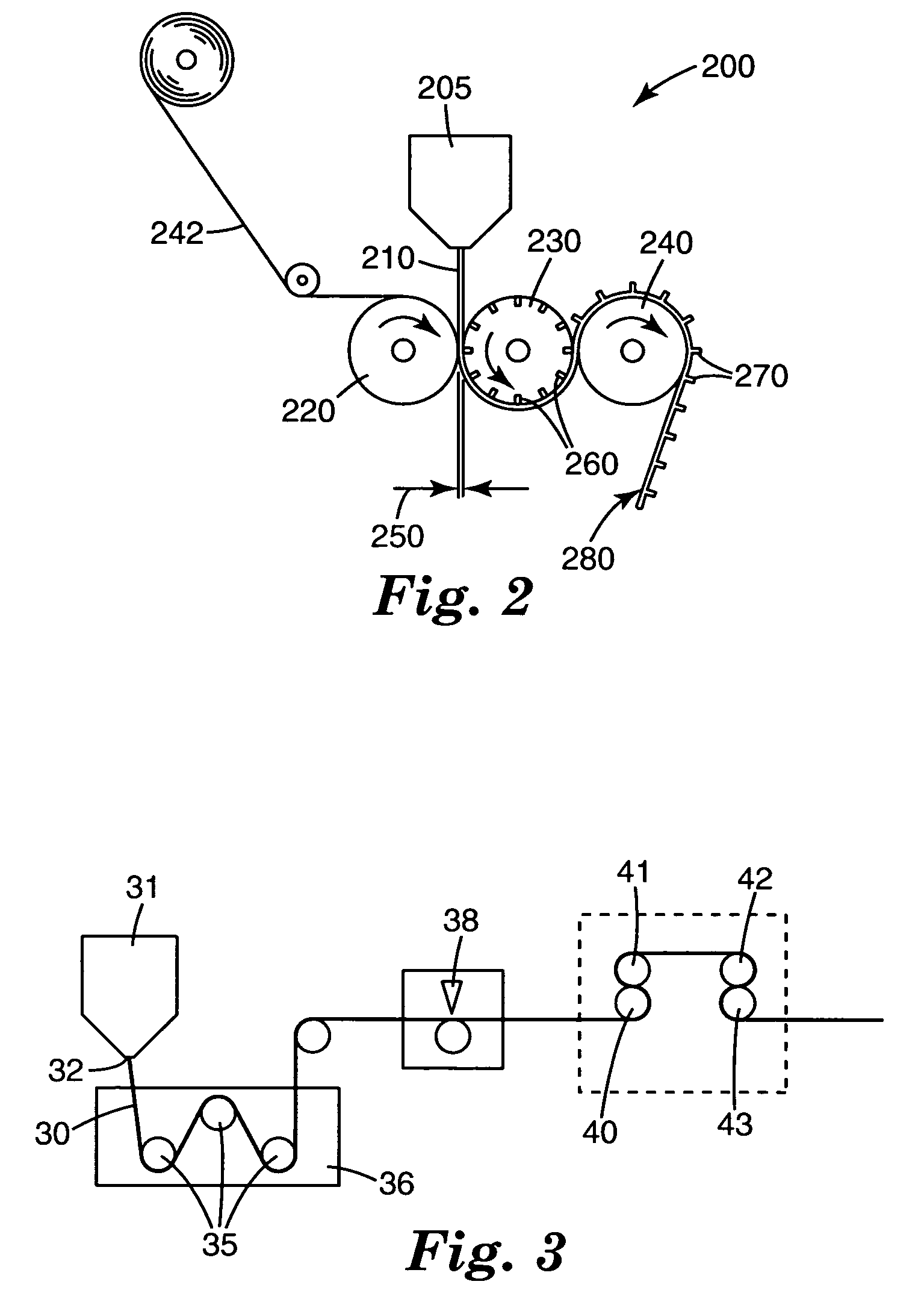
[0106]A flexible heat sink article was prepared using a process and apparatus such as illustrated in FIG. 2.

[0107]Pellets of Polymer A were fed into a single screw extruder (Model KTS-125 available from Killion Extruders, Inc. of Cedar Grove, N.J.) and melt-processed. The extruder had a diameter of about 3.2 cm (1.25 in), a screw speed of 80 rpm and a rising temperature profile from about 100° C. up to approximately 250° C. The Polymer A resin was conveyed through the extruder into a heated neck tube at 250° C. and finally into a 250° C. heated 15.2 cm (6 inches) wide sheet die with a maximum die lip opening of 0.102 cm (0.040 inch). The resin was continuously discharged from the sheet die at a pressure of 17.2 MPa (2500 psi) to form a molten polymer sheet.

[0108]Referring now to FIG. 2, molten polymer sheet 210 formed as described above 15 was introduced into nip 212 between nip roll 220 and cast roll 230 of a horizontal stack of three temperature-controlled, rotating, 30.5 cm (12 i...

example 2

[0112]Two flexible heat sink articles (2A and 2B) as shown in FIG. 7 were prepared by melt replication from Polymer C and Polymer D using a silicone mold.

[0113]The silicone mold used to produce heat sink article as shown in FIG. 7 was prepared by casting Silicone Resin onto a commercially available aluminum heat sink. The resin was allowed to cure overnight at room temperature and the cured resin was removed from the heat sink to provide a silicone mold.

[0114]One or two 1.18 cm (3 inches) long by 1.18 cm (3 inches) wide by 0.32 cm (⅛ inch) thick plaques of either Polymer C (to make heat sink article 2A) or Polymer D (to make heat sink article 2B) were aligned on the mold, then sandwiched between silicone coated paper liners, and melt pressed at 190° C. (374° F.) and a pressure of 454.5 kg (0.5 tons) for about 10 seconds followed by quenching on a cold press for 30 seconds. A thin layer of mold release agent was sometimes applied to the surface of silicone mold prior to melt pressing...

example 3

[0117]A heat sink article as shown in FIG. 8 was prepared as in Example 2, using a silicone mold and Polymer C. The silicone mold was prepared from a commercially available aluminum heat sink.

[0118]The resultant heat sink article had a square matrix design of polymeric protrusions that were tapered on one side. The width of the tapered side of the protrusion was about 1.6 mm (0.63 inch) at the top and about 2.2 mm (0.87 inch) at the point where the projection joined the base. The width of the straight side of the protrusion was about 2.5 mm (0.098 inch). The height of each projection was about 9 mm (0.35 inch) and the center-to-center spacing of the projections was about 5 mm (0.2 inch). The thickness of the heat sink article base was about 1.7 mm (0.067 inch).

[0119]The heat sink article was tested for cooling performance and wet-out capability on a concave surface with 9882 adhesive. The wet-out capability was lower than later samples because the base surface of this early prototyp...


PUM

PropertyMeasurementUnit
flexural modulusaaaaaaaaaa
aspect ratioaaaaaaaaaa
heightsaaaaaaaaaa

Abstract

Provided is a flexible heat sink article comprising a base comprising a polymer and a plurality of polymeric protrusions extending away from the base, each protrusion having a major dimension and a minor dimension. The base comprises thermally conductive particles, and the protrusions comprise non-spherical thermally conductive particles substantially aligned in the direction of the major dimension within the protrusions. A thermal interface material may be provided contiguous with the base. Also provided is a flexible heat sink article comprising a base comprising a polymer and having a first surface and a second surface, a plurality of polymeric protrusions extending away from the first surface of the base, each protrusion having a major and a minor dimension, and a metallic layer contiguous with the second surface of the base, wherein the base and the protrusions comprise thermally conductive particles. Also provided is a method of making a flexible heat sink.

Description

CROSS REFERENCE TO RELATED APPLICATIONS[0001]This application is a continuation of and claims priority to U.S. application Ser. No. 10 / 324,759, filed Dec. 19, 2002, now U.S. Pat. No. 6,919,504, the entirety of which is herein incorporated by reference.TECHNICAL FIELD[0002]This invention relates to flexible polymeric heat sink articles including those provided in a roll or tape form, as well as methods of making heat sink articles.BACKGROUND[0003]Heat sinks conduct thermal energy away from a heat-generating component to the environment by convection, radiation, or further conduction. Heat sinks usually have an extended surface area to improve heat dissipation to the environment. Aluminum (or other metal such as copper) extrusions are a common form of heat sink. These extrusions have a rigid base and extended surface area fins. The metal heat sinks are normally electrically conductive, and may contribute to electromagnetic interference problems in electronic devices. Other versions of...

Claims


Application Information

Patent Timeline
Patent Type & Authority Patents(United States)
IPC IPC(8): H05K7/20F28D15/02F28F3/02F28F3/04H01L23/367H01L23/373
CPCF28D15/0241F28F3/04H01L23/3677H01L23/3733H01L23/3735F28F3/022Y10T29/49366H01L2224/73253H01L2924/0102H01L2924/01025H01L2924/01046H01L2924/01078H01L2924/01079H01L2924/3011H01L2924/01019H01L2924/01021H01L2924/01055H01L2924/01322
Inventor MCCUTCHEON, JEFFREY W.NARUM, TIMOTHY N.SOO, PHILIP P.LIU, YAOQI J.
Owner 3M INNOVATIVE PROPERTIES CO
Why Eureka
Try Eureka