Generating system with a regulated permanent magnet machine and an active rectifier

a permanent magnet machine and active rectifier technology, applied in the direction of electric generator control, control system, dynamo-electric machines, etc., can solve the problems of increasing reducing weight, cost and complexity of electrical power generation systems, and no convenient means of altering magnetic flux

Active Publication Date: 2008-07-15
HAMILTON SUNDSTRAND CORP +1
View PDF3 Cites 22 Cited by
  • Summary
  • Abstract
  • Description
  • Claims
  • Application Information

AI Technical Summary

Problems solved by technology

Due to the rotational velocity limitations of the WFSM, such electrical power generation systems generally require a reduction gearbox between the prime mover and the WFSM.
This increases weight, cost and complexity of the electrical power generation systems.
This results in reduced weight, cost and complexity of an electrical power generation system.
However, a traditional PM PMM, with its permanent magnet rotor, has no convenient means to alter magnetic flux of the PMM rotor field that passes through its stator to regulate its output.

Method used


Image

  • Generating system with a regulated permanent magnet machine and an active rectifier
  • Generating system with a regulated permanent magnet machine and an active rectifier

Examples


Embodiment Construction

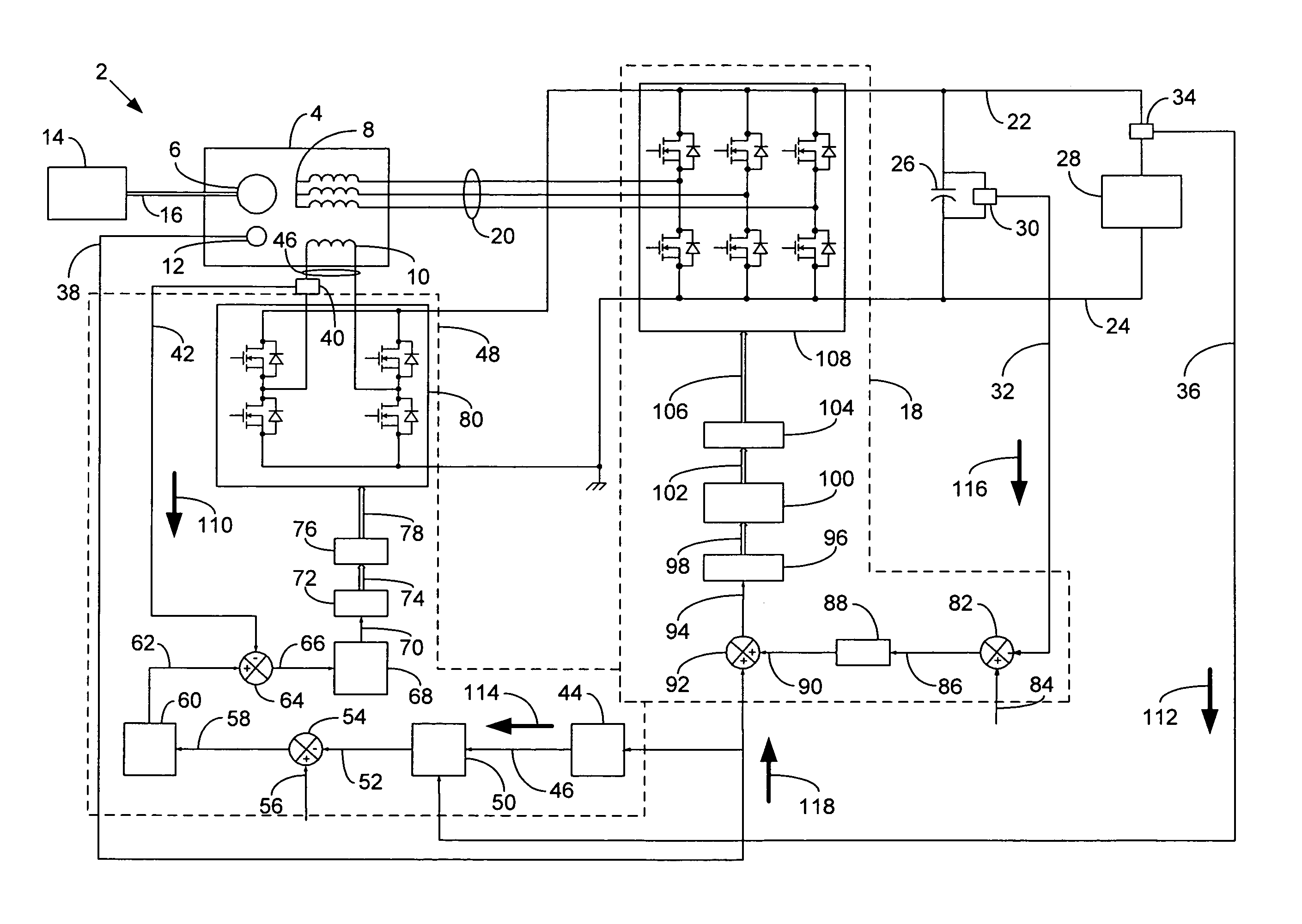
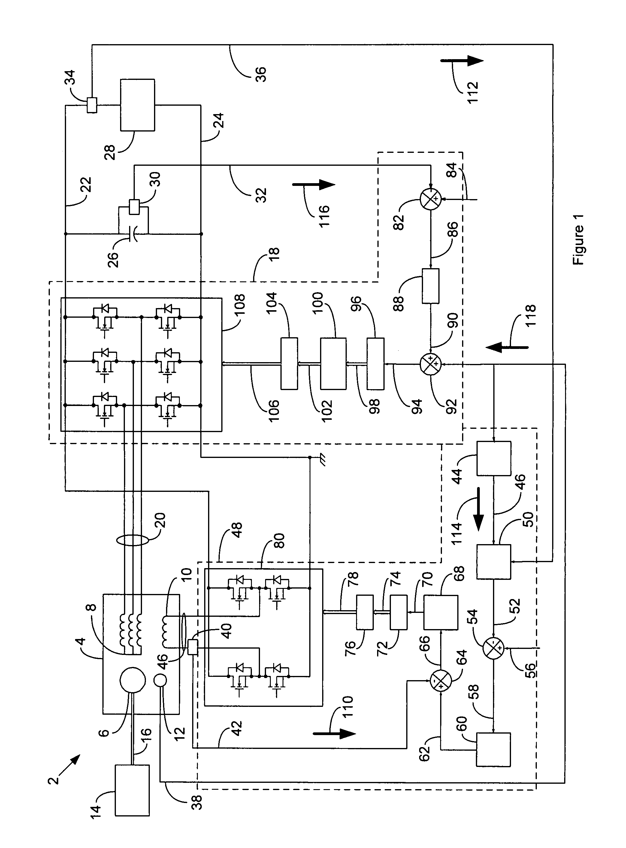
[0006]FIG. 1 is a high-level schematic diagram of an electrical power generation system 2 according to a possible embodiment of the invention. The electrical power generation system 2 comprises a PMM 4 that comprises a permanent magnet (PM) rotor 6, a stator 8, a control coil 10 and a position sensor 12. The rotor 6 comprises a permanent magnet type rotor. The stator 8 comprises a multiphase alternating current (AC) stator winding that is typically three phase AC. The control coil 10 comprises a winding in proximity to the stator winding 8 that is capable of generating a magnetic field with flux that passes through the stator winding 8 upon application of electrical current through the control coil 10. The position sensor 12 may be of any convenient type that is suitable for establishing the rotary position of the rotor 6. PMM 4 may have any suitable construction. An example of a suitable construction is found in co-pending application Ser. Nos. 10 / 996,411 and 11 / 420,614, by Dooley,...


PUM


Abstract

An electromechanical power transfer system that transfers power between a prime mover and a direct current (DC) electrical system, comprises: a permanent magnet machine (PMM) that has a permanent magnet (PM) rotor coupled to the prime mover, a stator with a multiphase alternating current (AC) winding coupled to an AC bus and a control coil with a winding that has a configuration to generate a magnetic field with flux that varies the reactance of the stator winding with the application of control coil current; a control coil current sensor for generating a control coil current signal that is representative of the level of electrical current in the control coil; an electrical current sensor for generating a DC bus current signal that is representative of the level of DC current through the DC bus; an electrical potential sensor for generating a DC bus potential signal that is representative of the level of DC potential on the DC bus; a fixed pattern active rectifier and inverter system coupled between the AC bus and a DC bus; a position sensing system for generating a rotor position signal that is representative of the angular position of the PM rotor; and a control coil current regulator system that regulates the control coil current.

Description

FIELD OF THE INVENTION[0001]The invention relates to electric power generation systems, and more particularly to prime mover powered electric power generation systems capable of delivering direct current (DC).BACKGROUND OF THE INVENTION[0002]Electrical power generation systems powered by variable speed prime movers that require highly regulated electrical output, such as electrical power generation systems used for aeronautical applications, generally use a wound field synchronous machine (WFSM) that serves as an electrical generator. This is because it is easy to adjust rotor current to regulate electrical output of a WFSM. In aeronautical applications, the prime mover is often a gas turbine engine that has a normal rotational velocity that exceeds 20,000 revolutions per minute (rpm). Due to the rotational velocity limitations of the WFSM, such electrical power generation systems generally require a reduction gearbox between the prime mover and the WFSM. This increases weight, cost...

Claims


Application Information

Patent Timeline
Patent Type & Authority Patents(United States)
IPC IPC(8): H02K29/06
CPCH02P9/10H02P9/48H02P9/305H02P2207/076
Inventor ROZMAN, GREGORY I.MADDALI, VIJAY K.DOOLEY, KEVIN
Owner HAMILTON SUNDSTRAND CORP
Why Eureka
Try Eureka