Grooved coaxial-type transmission line, manufacturing method and packaging method thereof

a coaxial transmission line and groove technology, applied in the direction of waveguides, waveguide type devices, printed circuit aspects, etc., can solve the problems of limited use of microstrip transmission lines, signal interference, and hole formation, so as to prevent radiative signal loss of signal lines, remove signal interference, and reduce the dimension of rf electrical equipment

Inactive Publication Date: 2008-07-15
KOREA ADVANCED INST OF SCI & TECH
View PDF3 Cites 53 Cited by
  • Summary
  • Abstract
  • Description
  • Claims
  • Application Information

AI Technical Summary

Benefits of technology

[0015]Accordingly, the present invention has been made keeping in mind the above problems occurring in the prior art, and an object of the present invention is to provide a coaxial transmission line, which prevents a radiative signal loss of signal lines during transmission of an RF signal, and removes signal interference between adjacent signal lines while allowing the signal lines to be compactly arrayed on an integrated circuit, thus reducing a dimension of RF electrical equipment using the transmission line system.

Problems solved by technology

However, the microstrip-type transmission line system has a problem in that a via hole must be formed to connect the signal line provided on the upper surface of the substrate to the ground wire provided on the lower surface of the substrate.
Thus, the microstrip-type transmission line system has been limitedly used for a substrate made of a soft material which allows the via hole to be easily formed, such as a printed circuit board (PCB).
Since the signal lines in the above-mentioned transmission line systems are not shielded, that is, are open, radiative signal losses of the signal lines occur during the transmission of signals, and further, signal interference occurs due to the radiative signals.
However, it is difficult to execute such a method of building the shielding walls, thus undesirably causing an increase in the manufacturing costs.
Recently, as a frequency in RF electrical equipment and an output power of the equipment becomes higher, the signal interference is further increased.
However, such a method has problems in that it takes a longer time to manufacture the coaxial transmission line, and a stress is generated due to a difference in thermal expansive coefficient of interface between the polymer film and other material during the hot curing process, thus reducing yield.
However, the method of using the air layer has a problem in that it is difficult to manufacture the coaxial transmission line, thus incurring great expense.

Method used


Image

  • Grooved coaxial-type transmission line, manufacturing method and packaging method thereof
  • Grooved coaxial-type transmission line, manufacturing method and packaging method thereof
  • Grooved coaxial-type transmission line, manufacturing method and packaging method thereof

Examples


Embodiment Construction

[0027]Hereinafter, embodiments of the present invention will be described in detail with reference to the attached drawings.

[0028]Reference now should be made to the drawings, in which the same reference numerals are used throughout the different drawings to designate the same or similar components.

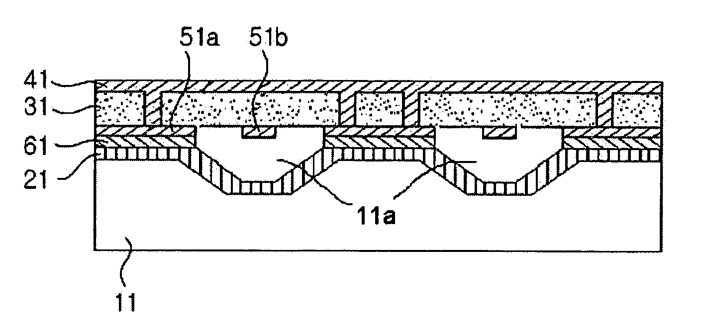
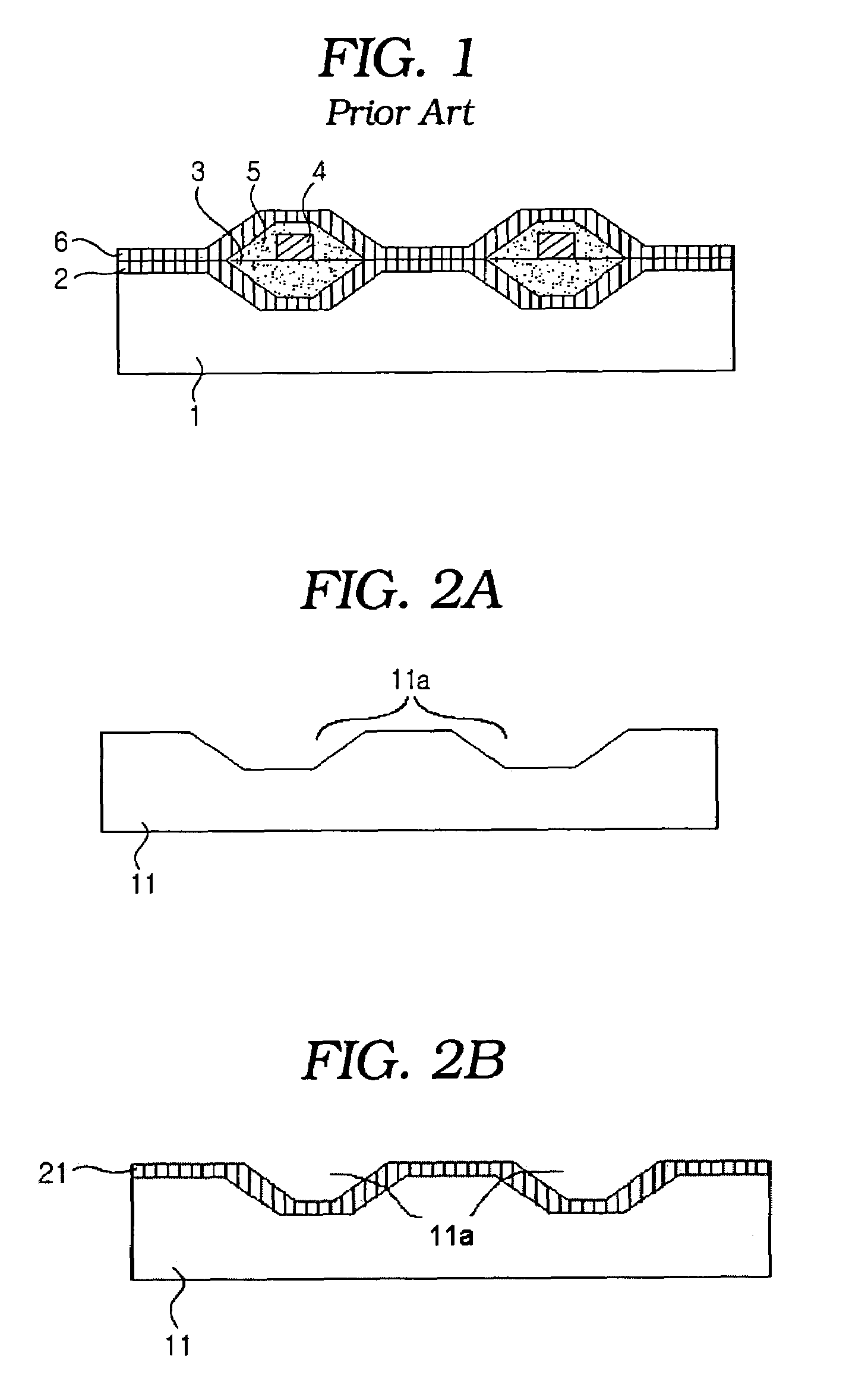
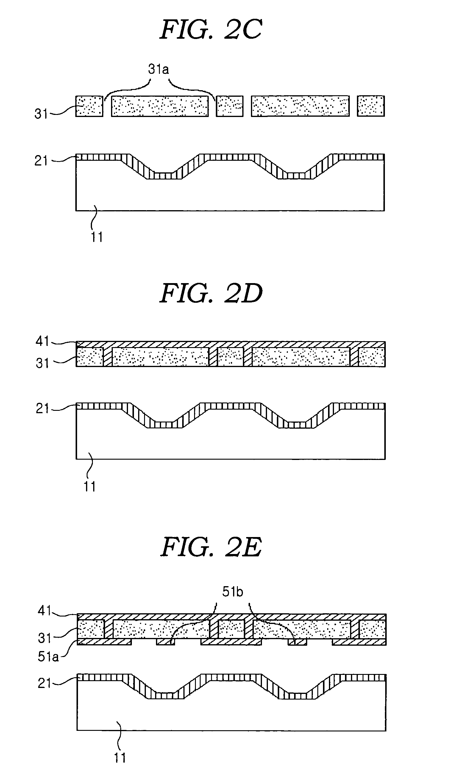
[0029]FIGS. 2a through 2h are sectional views to a method of manufacturing a coaxial transmission line using a dielectric film, according to the present invention. The manufacturing method will be described in detail in the following.

[0030]First, as shown in FIG. 2a, main grooves 11a are formed on a semiconductor substrate 11 using a semiconductor etching device to form a coaxial cross-section. At this time, a protective film covers prefabricated devices to prevent the devices from being etched.

[0031]Next, as shown in FIG. 2b, in order to form an outer ground layer of the coaxial transmission line, the substrate 11 and the main grooves 11a are plated with a metal, thus providing a first g...


PUM


Abstract

Disclosed herein are a transmission line of coaxial type and a manufacturing method thereof, capable of preventing a radiative signal loss of signal lines during transmission of an RF signal and removing signal interference between adjacent signal lines, thus allowing signal lines to be compactly arrayed during a manufacture of IC, and reducing a dimension of the IC. The transmission line of coaxial type includes grooves provided on a semiconductor substrate, a first ground layer, an electrically conductive epoxy coated on a flat part of the first ground layer except the grooves, second ground layers provided on the electrically conductive epoxy, a dielectric film provided at a position above the grooves and the second ground layers, a third ground layer provided on an upper surface of the dielectric film, and signal lines placed in spaces defined by the grooves and a lower surface of the dielectric film. In this case, the electrically conductive epoxy is coated on only contact surfaces of the first and second ground layers, and the signal lines are attached to the lower surface of the dielectric film.

Description

PRIORITY CLAIM[0001]This continuation-in-part application claims priority from Korean Patent Application No. 2003-63746 filed 15 Sep. 2003, which is incorporated herein by reference.BACKGROUND OF THE INVENTION[0002]1. Field of the Invention[0003]The present invention relates generally to transmission lines and more particularly, to a coaxial transmission line which reduces a signal loss during transmission of a radio frequency (RF) signal, and reduces signal interference between adjacent signal lines, and is manufactured by improved packaging technologies. Further, the present invention relates to a method of manufacturing the coaxial transmission line, and a method of packaging the coaxial transmission line.[0004]2. Description of the Related Art[0005]Typically, a coplanar-type transmission line system and a microstrip-type transmission line system have been widely used to transmit RF signals.[0006]The coplanar-type transmission line system is constructed so that a signal line and ...

Claims


Application Information

Patent Timeline
Patent Type & Authority Patents(United States)
IPC IPC(8): H01P3/06H01L27/00H01P11/00H05K1/02H05K3/46
CPCH01P3/06H01P11/005H05K1/0221H05K2201/09981H05K3/4614H05K2201/0379H05K2201/09809H05K1/0272H01L27/00
Inventor KWON, YOUNG SEKO, JU HYUNSHIN, SEONG HO
Owner KOREA ADVANCED INST OF SCI & TECH
Why Eureka
Try Eureka