
Frequency modulator, circuit, and method that uses multiple vector accumulation to achieve fractional-N frequency synthesis

a frequency modulator and multi-vector technology, applied in the field of electronic systems, can solve the problems of low frequency spur, high phase noise, and be too high for an intended application, and achieve the effect of less jitter and substantially reduced jitter

Inactive Publication Date: 2008-07-29
MONTEREY RES LLC
View PDF10 Cites 17 Cited by
  • Summary
  • Abstract
  • Description
  • Claims
  • Application Information

AI Technical Summary

Benefits of technology

"The patent describes an improved modulator circuit that solves problems in previous designs. The circuit produces a sequential pattern of values that are modulated about an average value. A divider in a PLL takes the modulated output and creates a fractional-N divide, resulting in a synthesized frequency with lower jitter. The circuit uses a delta-sigma modulator and a selector logic to choose the best value from a set of potential values. A multiplexer can be used to select the sum of the previous and current vectors, and the selection process can occur regularly or randomly. The method also involves modulating the frequency of a signal by selecting a vector from a set of vectors and using a divider in a PLL. The technical effects of this patent are improved performance and reduced jitter in frequency synthesizers."

Problems solved by technology

An unfortunate aspect of integer-N frequency dividers is that the selectable discrete frequencies of FVCO is dependent on the value of N. The frequency spacing, oftentimes referred to as the minimum frequency resolution, or minimum channel spacing, using an integer-N divider can, in some instances, be too high for an intended application.
Another issue is that for some applications, the integer N must be very large, and results in high phase noise.
A low frequency spur may therefore arise, and cannot be easily removed by the low-pass filter of the PLL.
This low frequency occurrence within the modulated output will produce substantial jitter in the pass band of the synthesized frequency.

Method used


Image

  • Frequency modulator, circuit, and method that uses multiple vector accumulation to achieve fractional-N frequency synthesis
  • Frequency modulator, circuit, and method that uses multiple vector accumulation to achieve fractional-N frequency synthesis
  • Frequency modulator, circuit, and method that uses multiple vector accumulation to achieve fractional-N frequency synthesis

Examples


Embodiment Construction

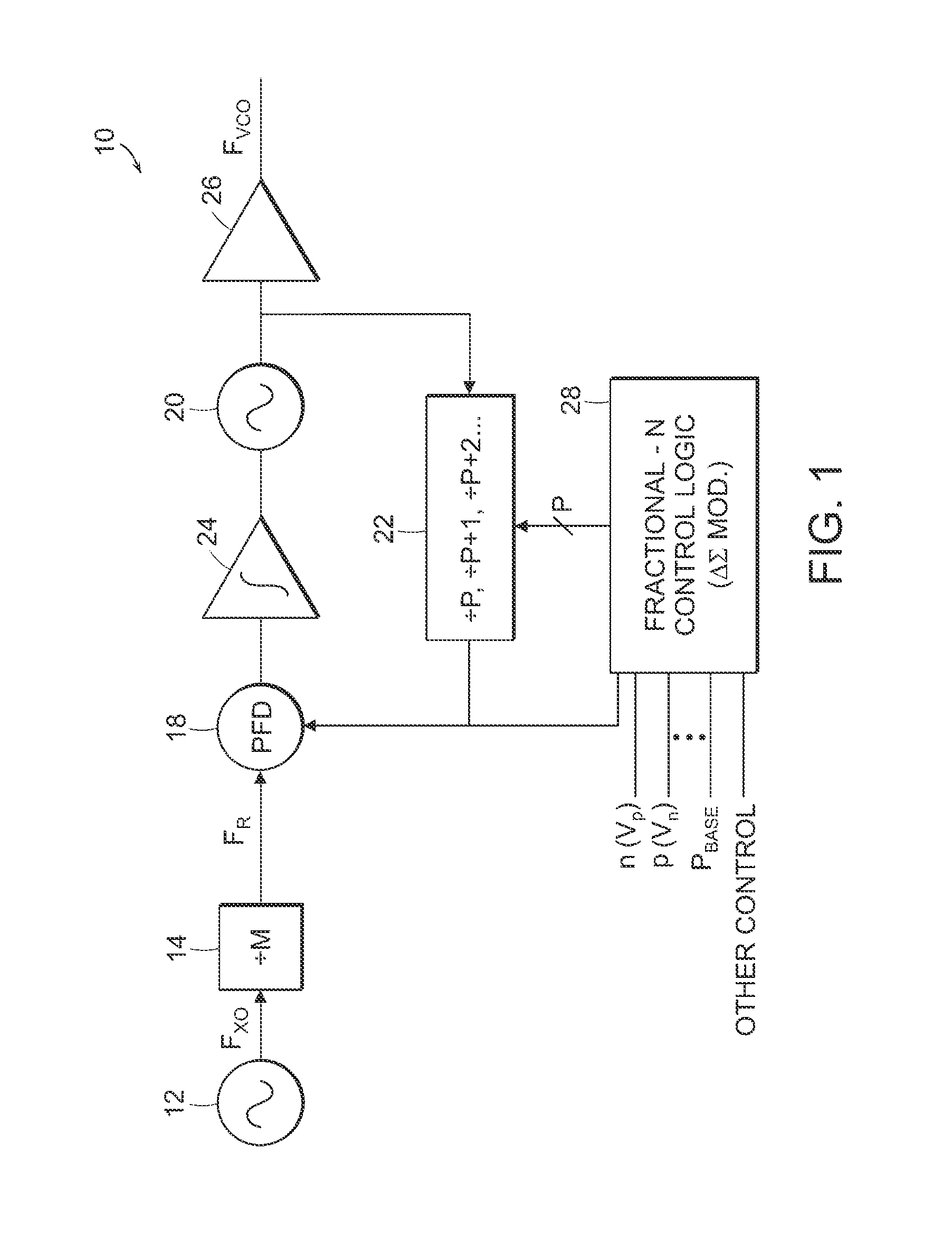
[0027]Turning now to the drawings, FIG. 1 is a block diagram of a frequency synthesizer 10 according to one form. Frequency synthesizer 10 contemplates the generation of multiple signal frequencies, all derived from a common reference or time base. The time base may be provided from a crystal oscillator 12. Crystal oscillator 12 includes any form of resonator such as, for example, quartz. The piezoelectric material, such as quartz, produces a piezoelectric effect that can be amplified, wherein the quartz operates as a feedback of low impedance at a particular resonant frequency.

[0028]Depending on how the quartz is formed or the crystal is cut, the resonant frequency can change. Typically, however, the resonant frequency is fixed for that particular resonator, with slight modifications to the output frequency available through trimming capacitors and the like. The output from the crystal oscillator thereby produces an alternating voltage or current at the resonant frequency FX as sho...


PUM


Abstract

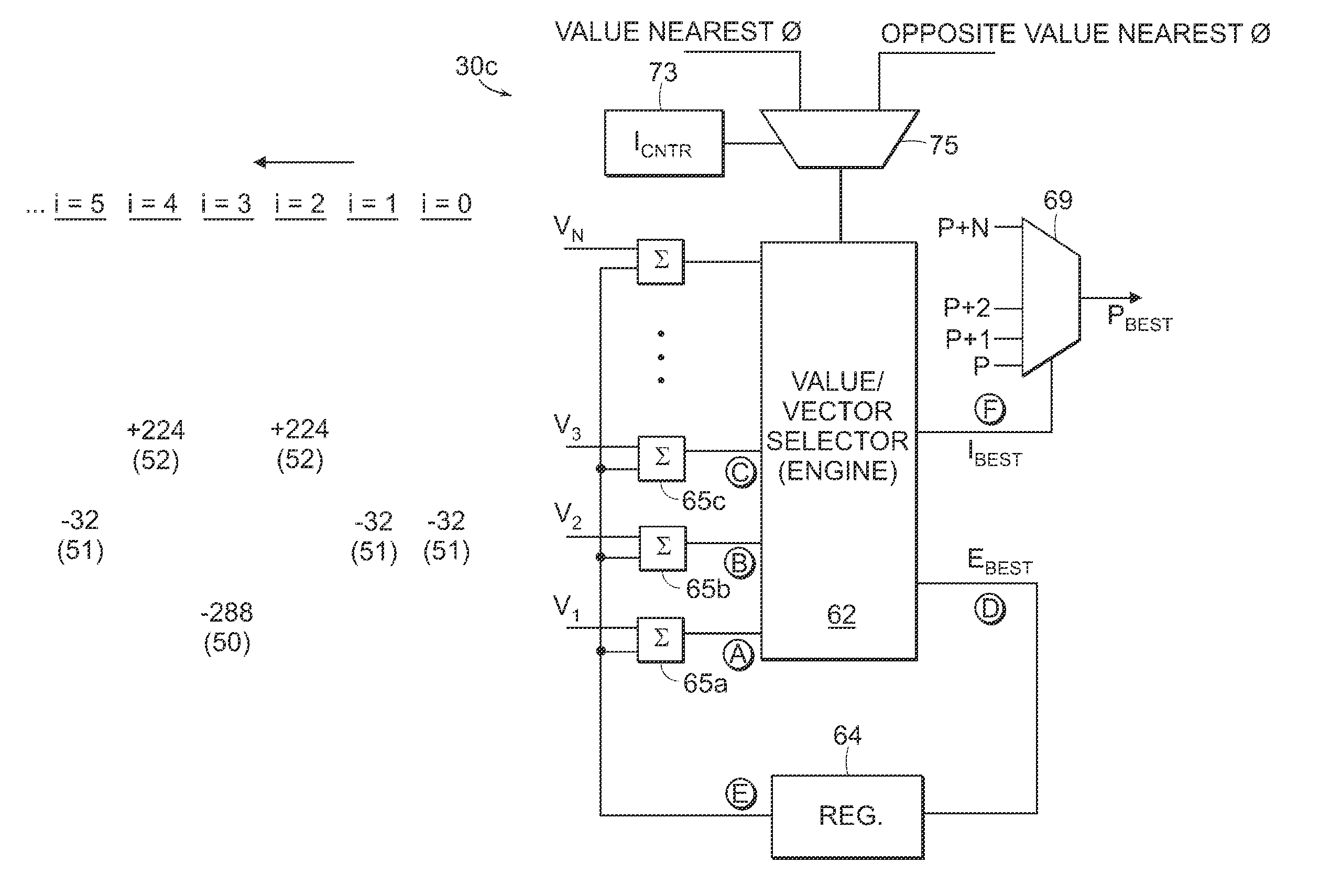
A frequency synthesizer is provided having a fractional-N control circuit and method. The control circuit can operate as having a modulator that selectively applies any fractional ratio to a frequency divider within, for example, a feedback loop of a PLL. The modulator can be a delta-sigma modulator or any sequential state machine that can be implemented as the control circuit, and can select amongst a plurality of vector values. The vector values can be spaced relatively close to each other, and the incoming present vector values can each be added to a value chosen from the immediately preceding set of potential values. The selector circuit chooses from among the present set of vector values depending on whether the sum is nearest a target value. The sum nearest the target value is, therefore, selected as the present vector value, and the process is repeated in time for each vector value having a corresponding P value to form a pattern of P values sent to the divider of the PLL. The incoming frequency can therefore be synthesized based on the modulated P values used by the feedback divider to produce the appropriate fractional-N divide ratio for the synthesized frequency.

Description

BACKGROUND OF THE INVENTION[0001]1. Field of the Invention[0002]The present invention relates to an electronic system and, more particularly, to a frequency modulator that can synthesize fractional-N frequency output using multiple vectors chosen to lower output jitter and increase selectivity and resolution of the fractional output.[0003]2. Description of the Related Art[0004]The following descriptions and examples are not admitted to be prior art or conventional by virtue of their inclusion within this section.[0005]Within nearly every electronic subsystem is some form of generator that produces cyclical waveforms. The waveform generator is oftentimes referred to as an oscillator. Oscillators can be rated depending on their stability and accuracy, frequency adjustability (i.e., tunability), and power consumption. The output from an oscillator is referred to as the reference frequency Fx. This reference frequency can thereafter be tuned using, for example, a phase-locked loop (PLL)...

Claims


Application Information

Patent Timeline
Patent Type & Authority Patents(United States)
IPC IPC(8): H03M3/02
CPCH03C3/0933H03C3/0925
Inventor LI, SHULIANG
Owner MONTEREY RES LLC
Learn More