Edge enhancement process and system

a technology of enhancement process and enhancement process, applied in image data processing, instruments, character and pattern recognition, etc., can solve the problems of existing edge enhancement process, jitter after enhancement, jagged edges, etc., and achieve the effect of reducing the visibility of jagged edges and reducing the enhancement on these edges

Inactive Publication Date: 2008-07-29
STMICROELECTRONICS ASIA PACIFIC PTE
View PDF13 Cites 41 Cited by
  • Summary
  • Abstract
  • Description
  • Claims
  • Application Information

AI Technical Summary

Benefits of technology

[0029]Preferred embodiments of the present invention, described hereinafter, rather than using edge detector based approach, can identify the maximum and minimum points within a local processing window with a max-min search component. However, unlike the process in described U.S. Pat. No. 6,094,205, only the maximum and minimum points closest to the pixel of interest in the local processing window are considered. The local maximum and minimum pixel values and their respective positions can be used to locate an edge center with sub-pixel precision, effectively resolving the jitter problem.
[0031]Generally, edges can be classified into soft, hard, semi-soft and semi-hard edges by considering simple edge properties such as transition width, transition height and transition slope. With constraints on enhancement based on these edge properties, mid-strength edges such as semi-soft and semi-hard edges are emphasized, whereas extreme soft and hard edges are de-emphasized, thus reducing the occurrence of over-enhancement artifacts and providing an enhanced image.
[0033]The max-min search component selects the two turning points nearest to the center of the processing window, one maximum and the other minimum, and that form a region encompassing the center pixel. This region contains the edge to which the center pixel belongs, and enhancement is then performed on this edge. The advantages are that close edges are handled in a generic way and “over-the-hill” problems are avoided.
[0034]To reduce the visibility of jagged edges after enhancement, an edge-directed filtering operation is performed prior to enhancement. This filtering smoothes fuzzy edges by averaging pixel values along selected edge directions and this affects the subsequently generated enhancement difference signal. An edge direction detector is used to detect the direction of edges, and directions close to the vertical are then subjected to pre-enhancement filtering because jagged edges are more noticeable in near-vertical edges.
[0035]On the other hand, edges closer to the horizontal exhibit undesirable aliasing effects especially after enhancement due to the expansion of the vertical frequency range above a subjectively acceptable level. Rather than applying post-processing such as vertical filtering on the enhanced signal, the enhancement on these edges is reduced according to the amount of vertical aliasing present, thus providing aliasing protection.

Problems solved by technology

Although peaking filters do not increase frequency components, they steepen the edges.
There are a number of difficulties with existing edge enhancement processes.
If the resulting error in the exact location of the edge becomes too large, jitter becomes visible after enhancement.
Generally, this problem only occurs when edge enhancement is based on the distance from the edge center that is identified by the pixel grid.
A second problem is the over-enhancement of soft and hard edges that results in an artificial-looking image.
Furthermore, when hard edges are steepened further, unnatural looking plateaus on both sides of the edge are generated.
Thirdly, edge processing methods are generally not robust to noise and often result in images with enhanced noise.
In methods based on detected edge centers, local processing masks used with 2nd derivative operators or Laplace operators locate edges most precisely, but are very sensitive to noise.
Stochastic gradient operators, on the other hand, are most robust to noise, but are not easy to implement as the level of noise changes.
Similarly, methods using peaking filters are very sensitive to noise.
A fourth problem is the inflexibility to handle close and complicated edges.
Generally in pixel level processing, special boundary conditions are made to cater for such situations but these may not be sufficient to cover all cases.
Another problem is the enhancement of fuzzy edges, resulting in obvious jagged edges.
They may be present due to randomness introduced on edges for special effects purposes or the deteriorating quality of old films.

Method used


Image

  • Edge enhancement process and system
  • Edge enhancement process and system
  • Edge enhancement process and system

Examples


Embodiment Construction

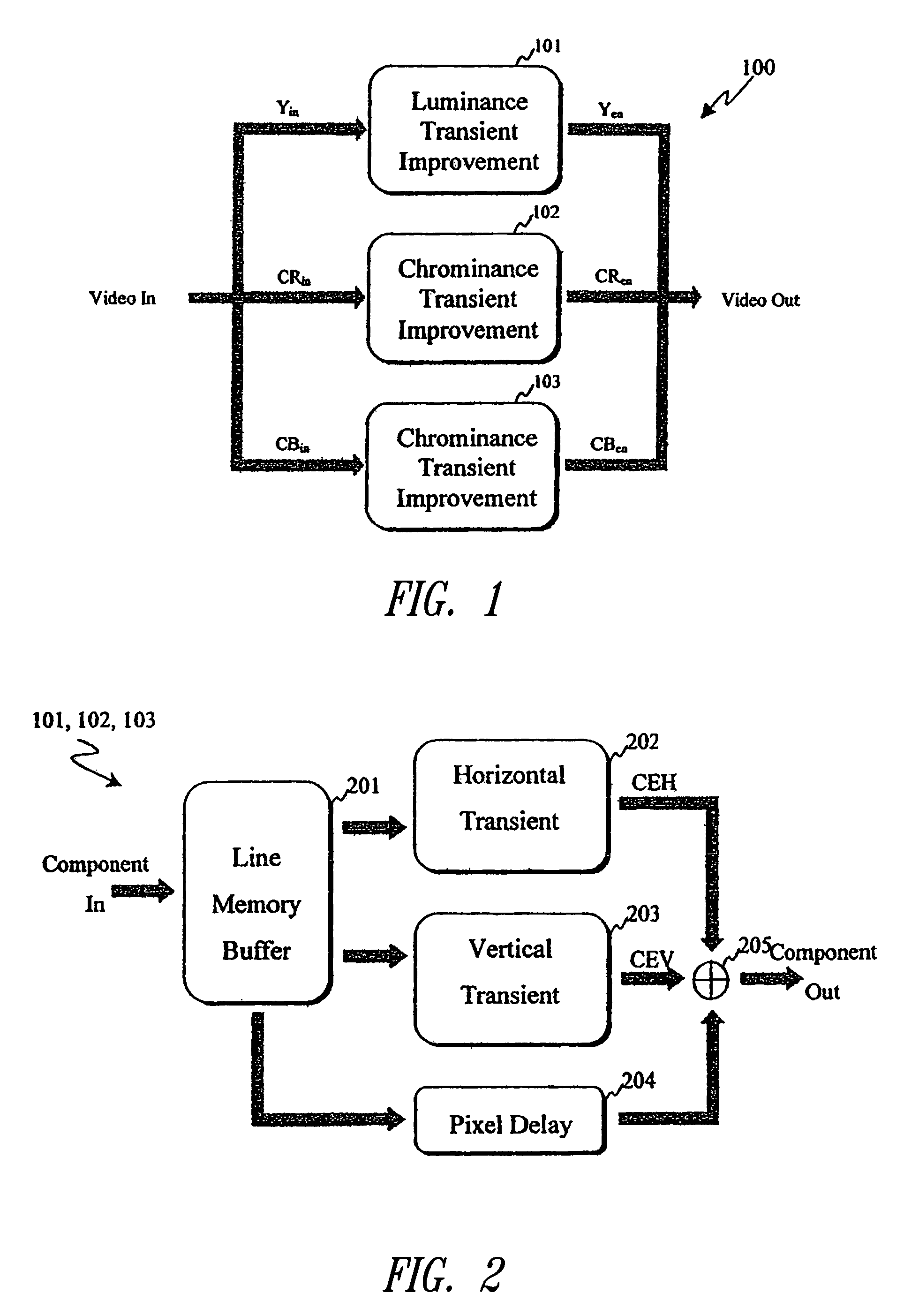
[0052]As shown in FIG. 1, an edge enhancement system 100 includes a luminance transient improvement circuit 101 and two chrominance transient improvement circuits 102, 103 for respective chrominance components. The edge enhancement system 100 executes an edge enhancement process to generate output image data with enhanced edge features from input image data. In the preferred embodiment, the edge enhancement process is implemented by hardware components of the edge enhancement system 100, including application-specific integrated circuits (ASICs). However, it will be apparent to those skilled in that art that at least parts of the edge enhancement process can alternatively be provided by one or more software modules executed by a digital signal processor (DSP) or other computing device, such as a standard computer system.

[0053]The edge enhancement system 100 can be used as a component in a variety of still and moving (i.e., video) image devices and systems. For example, the edge enha...


PUM


Abstract

An edge enhancement system, including a selective edge controller for determining one or more properties of an edge of image data, and for generating one or more weighting factors on the basis of properties of the edge; and a scaling module for scaling an edge enhancement signal by the weighting factors to control the degree of edge enhancement. The image data may represent a still or moving (i.e., video) image. A max-min search circuit determines maximum and minimum turning points closest to the center of the data processing window and that are located on opposing sides of the window, to determine values and locations of maximum and minimum pixels of the edge. An edge-directed pre-filtering circuit reduces the amplification of edge fuzziness by smoothing close the edges vertical prior to enhancement. An aliasing protection circuit reduces the visibility of saw-tooth defects on predominantly horizontal diagonal edges.

Description

BACKGROUND OF THE INVENTION[0001]1. Field of the Invention[0002]The present invention relates to an edge enhancement process and system for image data representing static or moving (i.e., video) images.[0003]2. Description of the Related Art[0004]Luminance transient improvement or enhancement refers to the sharpening of an image by steepening edge transitions on the luminance component of the image, thereby increasing the original signal bandwidth. There are two general approaches to making an edge steeper. One approach increases pixel values on the high side of an edge and decreases pixel values on the other side of the edge, thereby making a gradual transition more abrupt. The other approach is to replace pixel values near the edge with pixel values further away from the edge.[0005]In general, existing transient improvement circuits are based on one of three transient improvement techniques. The first technique uses edge detectors. Usually, the center of the edge is located and th...

Claims


Application Information

Patent Timeline
Patent Type & Authority Patents(United States)
IPC IPC(8): G06K9/40G06K9/48G06T5/00
CPCG06T5/003G06T2207/20192G06T2200/12
Inventor CHIANG, PATRICIA WEI YIN
Owner STMICROELECTRONICS ASIA PACIFIC PTE
Why Eureka
Try Eureka