Automated filament attachment system for vacuum fluorescent display

a vacuum fluorescent display and filament attachment technology, applied in the direction of auxillary welding devices, forging/pressing/hammering apparatuses, electric discharge tubes/lamps, etc., can solve the problems of inferior or damaged displays, system cost, and increased overall thickness of structures, so as to prevent filament from catching or snagging

Inactive Publication Date: 2008-08-05
ORTHODYNE ELECTRONICS
View PDF36 Cites 13 Cited by
  • Summary
  • Abstract
  • Description
  • Claims
  • Application Information

AI Technical Summary

Benefits of technology

[0011]According to another embodiment, a filament or wire clamp, located adjacent to the filament guide of the bond tool, has opposing clamp halves that form a small curved taper opening at the wire entry side, with the sides of the halves extending away from each other such that the wire exit side is wider than the gripping region. The curved entry prevents both the coating or material from being removed from the filament and the filament from catching on the clamp upon entry. As the coiled filament passes through entry, the filament will hit the diverging walls of the opposing clamp halves, which will help the filament “tail” to stay straight upon exit from the clamp.
[0012]According a further embodiment, a de-spooling system, with a balanced dancer arm and spool, is located on the bond head. The dancer arm applies the necessary tension (e.g., similar tension applied during winding) to the filament as the filament is unwound from the spool. This aids in preventing the filament from catching or snagging (e.g., with underlying layers of filament on the spool), which would otherwise result in the filament coating flaking off. Because the de-spooling system is located on the bond head and, for example, not on top of the machine, any coating that does flake off will not drift into the machine and / or onto the path of the filament feed.

Problems solved by technology

However, such a system can be costly due to the additional expense of manufacturing and securing the support structures onto the device.
Furthermore, the support structures increase the overall thickness of the device.
Moreover, the welding of the filament to the support structures may cause the filament coating, e.g., carbonate, to scatter into display areas of the device, thereby resulting in inferior or damaged displays.

Method used


Image

  • Automated filament attachment system for vacuum fluorescent display
  • Automated filament attachment system for vacuum fluorescent display
  • Automated filament attachment system for vacuum fluorescent display

Examples


Embodiment Construction

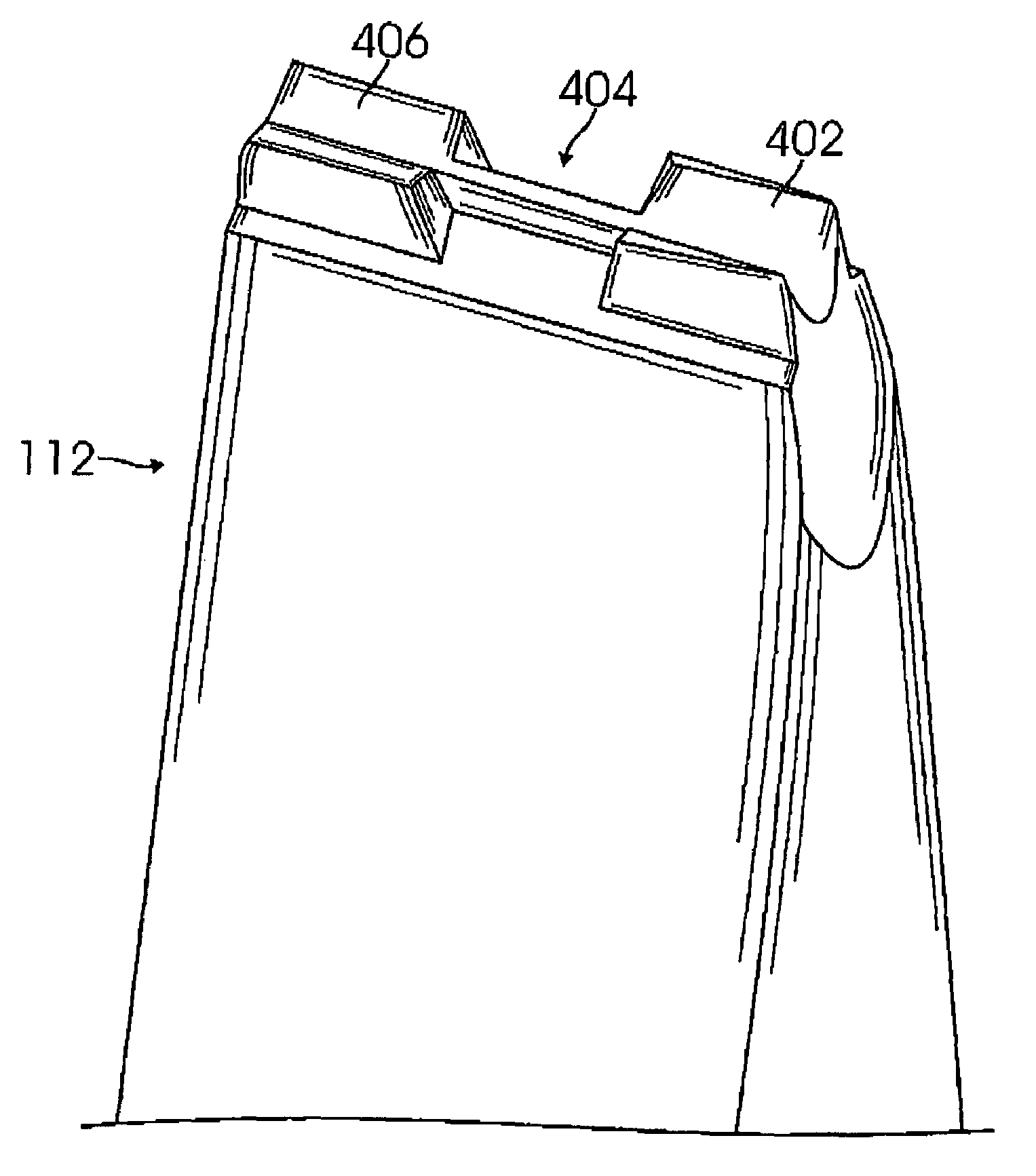
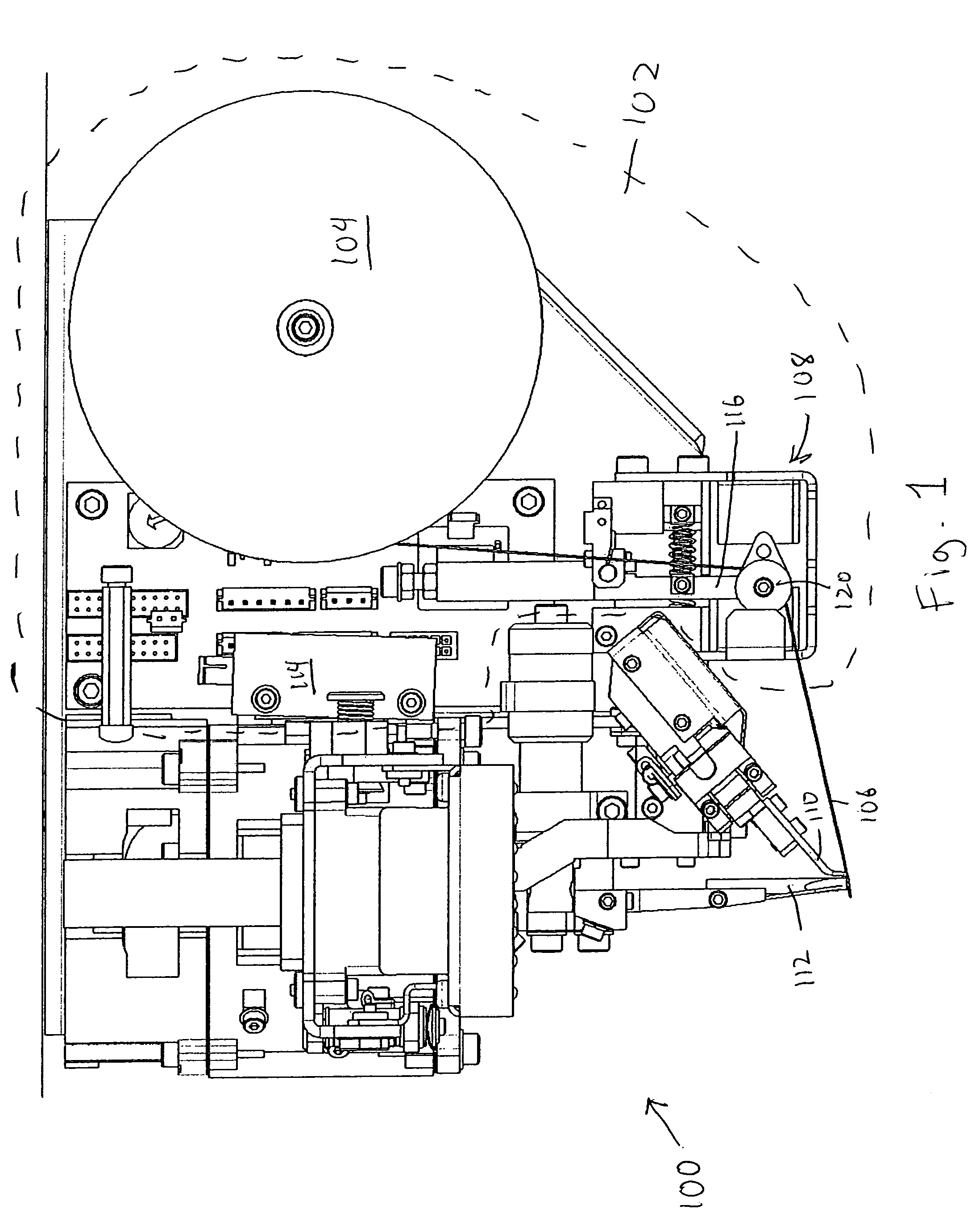
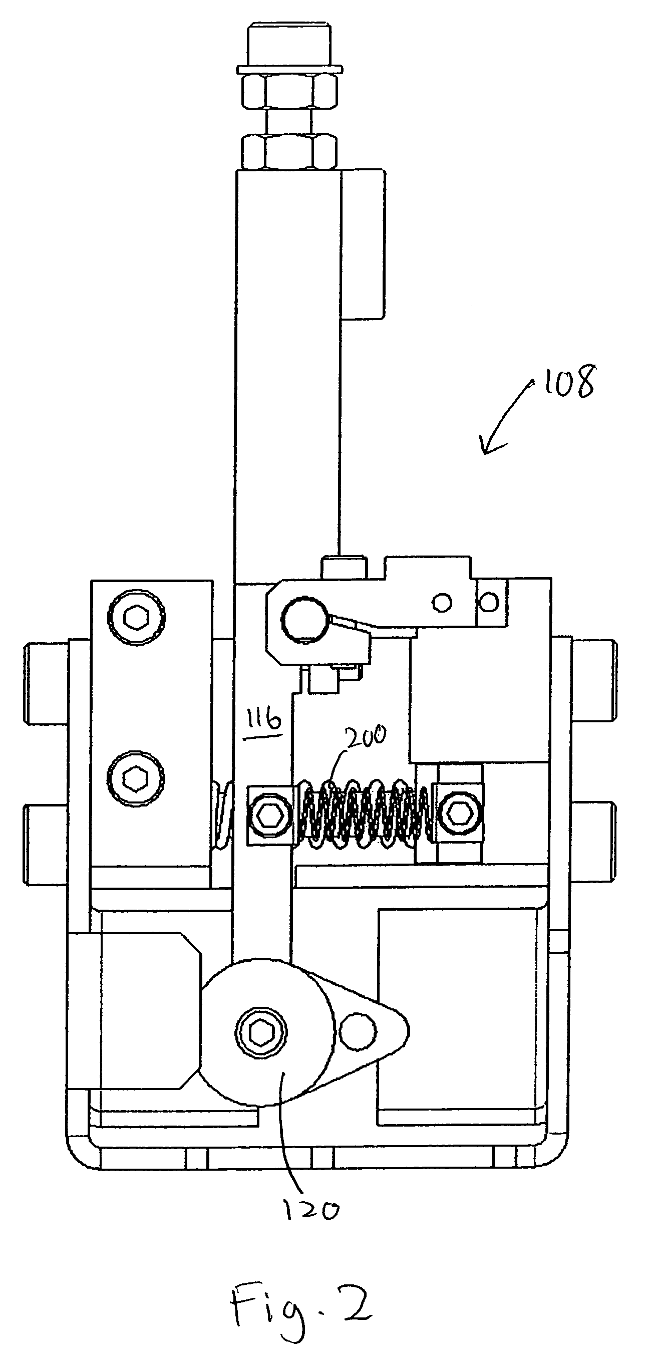
[0024]FIG. 1 shows a bond head 100, as part of a filament or wire attachment system, according to one embodiment of the invention. Bond head 100 includes a de-spooling system 102 having a spool or reel 104 wound with a filament or wire 106 and a balanced dancer arm assembly 108, a filament or wire clamp 110, and a bond tool 112.

[0025]De-spooling system 102, according to one embodiment, is located on bond head 100. De-spooling system 102 includes a stepper motor 114 mechanically driving spool 104. Spool 104 is driven by motor 114 in an incremental manner. Motor 114 can be a two phase bi-polar load motor or any other stepper motor which does not spin freely. Also, to prevent free spinning of other types of drives, electromotive movement motors, servos or coils, a brake or drag system with the electromotive drive can be utilized. Motor 114 drives spool 104 incrementally, as filament 106 is unwound from spool 104, and thus, spool 104 is free to continuously rotate. Stepper motors in ope...


PUM

PropertyMeasurementUnit
thicknessaaaaaaaaaa
thicknessaaaaaaaaaa
thicknessaaaaaaaaaa

Abstract

A filament attachment system includes a bond head comprising a de-spooling system with a spool and balanced dancer arm assembly, a clamp having a curved filament entry, a narrower gripping region, and a wider filament exit, and a bond tool comprising a guide portion, a grooving portion, and a staking portion. The grooving portion forms a groove into a bond and the staking portion closes the groove over the filament, securing the filament in the bond. Thus, the filament can be attached with a single pass of the bond head using a single bond.

Description

BACKGROUND[0001]1. Field of the Invention[0002]The present invention relates to wire bonding devices, and in particular, to such bonding devices that attach filament.[0003]2. Related Art[0004]Conventional systems and methods for attaching filament to devices, such as semiconductor chips or displays, typically include a spool of filament, a de-spooler to unwind the filament, a dancer arm with a pulley to adjust tension in the filament as it is unwound, a filament guide, and an attaching means for attaching the filament. The attaching means may be a welding device, such as a laser welder or ultrasonic bonder. The device onto which the filament is to be attached can be held in place, while the attaching means moves to attach the filament at the selected portions of the device. Other types of spooled lines, such as bond wires, may utilize similar structures and methods.[0005]Conventional devices include support structures onto which the filament is stretched across and attached, such as...

Claims


Application Information

Patent Timeline
Patent Type & Authority Patents(United States)
IPC IPC(8): B23K37/00B23K37/04B21F23/00B21K25/00B23K20/00H01J9/02H01K3/06H01L21/607
CPCB21K25/00B23K20/005H01K3/065H01L24/78H01L24/85H01L2224/45124H01L2924/01033H01L2924/01023H01L2924/01005H01L2924/20752H01L2924/01075H01L2924/01074H01L2924/01056H01L2924/01038H01L2924/0102H01L2224/45015H01L2224/48011H01L2224/48091H01L2224/48472H01L2224/78313H01L2224/786H01L2224/851H01L2924/01006H01L2924/01013H01L2924/00014H01L2924/20642H01L2924/00H01L24/45H01L24/48H01L2224/85205H01L2924/12042
Inventor COPPERTHITE, THEODORE J.WALKER, TODD J.BABAYAN, VARTANNICHOLLS, MARTIN R.
Owner ORTHODYNE ELECTRONICS
Why Eureka
Try Eureka