
Process for separating NH3 , and optionally also CO2 and H2O, from a mixture containing NH3 , CO2 and H2O

a technology of nh3 and co2 is applied in the field of separating nh3 from a mixture containing nh3 and optionally co2 and h2o, which can solve the problems of difficult control of nhsub>3/sub>separation devices, increased steam consumption, and increased risk of solid formation, so as to reduce energy consumption and reduce the effect of nh3 separation and separation, and increase the operational possibilities of composition

Active Publication Date: 2008-08-05
STAMICARBON BV
View PDF11 Cites 2 Cited by
  • Summary
  • Abstract
  • Description
  • Claims
  • Application Information

AI Technical Summary

Benefits of technology

[0007]An advantage of the process according to the invention is that the danger of solids being formed in the NH3 separation device is less than in the known NH3 separation device. This reduces the need for efficiency-impairing measures such as the said water flushing operation, so that the process is more stable at a lower consumption of energy, for example in the form of steam, and as a result is cheaper.
[0008]Without intending to give a theoretical explanation of the advantages of the process according to the invention, it is being assumed that the conversion to a liquid phase of CO2 has such an effect on the ratios in the NH3 rectification step between NH3, CO2 and H2O and / or the phase in which they are present that there is less danger of solids being formed. In addition, it is being assumed that it is possible to enlarge the operational possibilities of composition, pressure and temperature in the NH3 separation device in such a way that there is less danger of solids being formed.
[0022]If the condensation step according to the invention is applied to the stream consisting substantially of gaseous NH3, this is done preferably in a submerged condenser with an aqueous stream and / or liquid NH3 being supplied as absorbing medium. A submerged condenser is known per se, for example from NL 8400839 A. The aqueous stream consists substantially of water but may in addition also contain other compounds; examples are NH3, CO2, ammonium carbamate, melamine or urea. In the submerged condenser the stream consisting substantially of gaseous NH3 comes into direct contact with the also supplied aqueous stream and / or liquid NH3, in which CO2 will absorb. This has the advantage that less stringent requirements are specified for the CO2 removal in the NH3 separation device than in the known process, which enhances the operational stability and reduces the risk of solids being formed. As stated earlier, the formation of solids leads to steam consumption that is occasionally and / or structurally higher. Also, through the choice of the feed streams and their temperatures, optimum heat transfer and mass transfer conditions can be chosen, which is especially favourable as regards the transition of CO2 from the gas phase to the liquid phase in the submerged condenser.
[0024]In another embodiment of the condensation step according to the invention this step is carried out as a partial condensation step on the stream that comes from the desorption device and that is supplied to the NH3 separation device. The partial condensation step is preferably carried out by means of indirect cooling with a cooling medium, in for example a heat exchanger. The stream coming from the desorption device also contains H2O and NH3; as a result of the partial condensation step at least a part of the H2O will become liquid, in which a part of the CO2 is absorbed as well as a part of the NH3. As a result, operation of the NH3 separation device becomes simpler, and more stable on account of a smaller risk of solids being formed. Preferably the mixture present in the NH3 separation device is used as cooling medium in the partial condensation step.

Problems solved by technology

A disadvantage of the known process is that the NH3 separation device is difficult to control.
The composition, pressure and temperature are such that normal fluctuations in the process operation entail the danger of solids being formed.
As stated earlier, the formation of solids leads to steam consumption that is occasionally and / or structurally higher.

Method used


Image

  • Process for separating NH3 , and optionally also CO2 and H2O, from a mixture containing NH3 , CO2 and H2O
  • Process for separating NH3 , and optionally also CO2 and H2O, from a mixture containing NH3 , CO2 and H2O
  • Process for separating NH3 , and optionally also CO2 and H2O, from a mixture containing NH3 , CO2 and H2O

Examples


Embodiment Construction

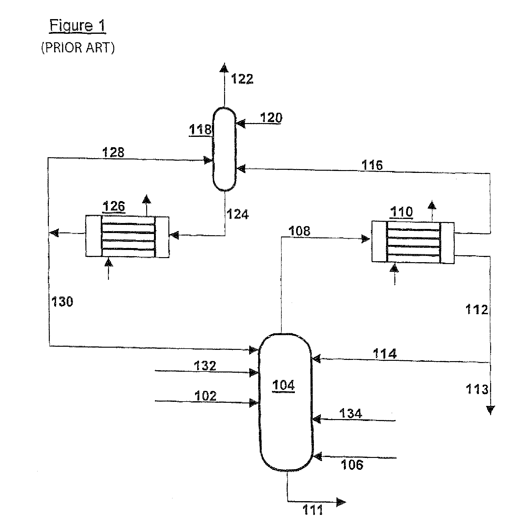
[0029]In FIG. 1 a mixture of NH3, CO2 and H2O is supplied via line 102 to NH3 separation device 104, which is designed as a distillation column and is preferably operated at a temperature between 15-160° C. and at a pressure between 0.1 and 6 MPa. Air is also supplied to the NH3 separation device 104, via line 106, to protect the equipment against corrosion. The stream consisting substantially of gaseous NH3 is discharged via line 108 to ammonia cooler 110; the mixture is discharged as a liquid solution of NH3 and CO2 in water via line 111 and transferred to a CO2 separation device—not drawn. In ammonia cooler 110 almost all NH3is liquefied and discharged via line 112, partly to be recirculated via line 114 to NH3 separation device 104, partly via 113 to be used elsewhere. From ammonia cooler 110 there also comes a gas phase, which consists substantially of inert gases and some NH3 and which is conveyed via line 116 to scrubber 118. In scrubber 118 the stream from line 116 is brough...


PUM

PropertyMeasurementUnit
wt %aaaaaaaaaa
pressuresaaaaaaaaaa
pressuresaaaaaaaaaa

Abstract

The invention relates to a process for separating NH3 from a mixture containing NH3, CO2 and H2O which comprises an NH3 rectification step carried out in a NH3 separation device to which one or more streams containing NH3, CO2 and H2O including the mixture, are supplied, with a stream consisting substantially of gaseous NH3 being formed in the NH3 separation device, separated from the mixture and discharged. In the process according to the invention a condensation step is carried out on at least one of the stream consisting substantially of gaseous NH3 or the one or more streams containing NH3, CO2 and H2O supplied to the NH3 separation device, in which at least a part of the existing CO2 is converted to a liquid phase.

Description

[0001]This application is the US national phase of international application PCT / NL2004 / 000014 filed 9 Jan. 2004 which designated the U.S. and claims benefit of NL 1022526, dated 30 Jan. 2003, the entire content of which is hereby incorporated by reference.BACKGROUND AND SUMMARY OF INVENTION[0002]The invention relates to a process for separating NH3 from a mixture containing NH3, CO2 and H2O which comprises an NH3 rectification step carried out in an NH3 separation device to which one or more streams containing NH3, CO2 and H2O, including the mixture, are supplied, with a stream consisting substantially of gaseous NH3 being formed in the NH3 separation device, separated from the mixture and removed.[0003]Such a process is known from NL 7804668 A. In the known process, which can find application in processes for the preparation of melamine or urea or the combined preparation of melamine and urea, the mixture supplied to the NH3 separation device is gaseous or liquid. The NH3 separati...

Claims


Application Information

Patent Timeline
Patent Type & Authority Patents(United States)
IPC IPC(8): C01C1/12
CPCC01C1/12Y02C20/40
Inventor BIERMANS, ANDREAS JOHANNESJONCKERS, KEESMENNEN, JOHANNES HENRICUSDE WIT, NORA ANNAHOOIJKAAS, HERBERT WILLEM GERRITVAN DE KERKHOVE, BASTIAAN RENE AGNES MARIE
Owner STAMICARBON BV
Learn More