Tunable optical routing systems

a technology of optical routing and multiplexing, applied in the field of wavelength division multiplexed optical communication systems, can solve the problems of low cost and low insertion loss, low per-wavelength routing flexibility of a wss, and the cost of oeo regeneration

Active Publication Date: 2008-08-05
CHRISTOPHER S KOEPPEN +1
View PDF7 Cites 26 Cited by
  • Summary
  • Abstract
  • Description
  • Claims
  • Application Information

AI Technical Summary

Benefits of technology

[0012]In accordance with one aspect of the invention, the two tilt axes enable substantially independent control of both a detected wavelength and optical power at such wavelength directed to the opto-electronic detection device.
[0021]In accordance with one aspect of the invention, the optical beam actuator has two tilt axes such that the two tilt axes enable substantially independent control of both the detected wavelength and the selection of input signal at such wavelength directed to the opto-electronic detection device.
[0024]In accordance with one aspect of the invention, the optical element has two tilt axes such that the two tilt axes enable substantially independent control of both the detected wavelength and the optical beam coupling between the input signals and the fiber outputs or the opto-electronic detection devices so as to select a number of round trips of the input signals through the diffraction element before being spectrally detected to thereby select spectral resolution.

Problems solved by technology

This economic justification has led to the transmission of large amounts of bandwidth in multiple wavelengths over a single fiber, and in turn has driven the need to flexibly route those wavelengths at the wavelength layer to avoid bandwidth scaling issues with electrical based switching (cost / size / heat dissipation / upgradability) as well as the expense of OEO regeneration that electrical switching requires.
In general these devices have low cost and low insertion loss, however the wavelength-dependent routing configuration is static and the intrinsic device provides for no control or feedback of the optical signals that flow through it.
Although this WSS technology is not yet mature, it seems quite likely that the premium performance and price of this technology will enable it to dominate signal control and monitoring applications in devices where flexible routing of many wavelengths is required.
For these reasons, the per-wavelength routing flexibility of a WSS is not nearly as valuable as in other parts of the network where mesh traffic patterns prevail.
Therefore it is likely that even though the WSS is more cost-effective than the other technology alternatives with equivalent functionality, it is likely too expensive to use at the edge of the network where the flexibility it provides may not add sufficient value.
Installation of new TFF filters breaks the optical path passing through a node, which is at the very least undesirable, and for many carriers unacceptable if signals from other nodes are interrupted.
This preplanning is not only time consuming, but also results in unused, stranded system capacity when capacity at that node does not materialize to meet the projected demand.
The second limitation is the concatenation of multiple banded TFFs and individual demultiplexing drop filters is a time-consuming, manually intensive process that requires skilled craftsmen.
The final limitation is this complex arrangement of filters can result in significant amounts of loss, including differential loss for different wavelengths.
These latter two problems prevent the equivalent automation of signal routing in the optical layer as has always been provided in the electrical layer.
This combination of non-automated, manual, and skill-intensive configuration procedures creates a barrier to fast deployment of DWDM at the edge of the network, and is in general an impediment to rapid deployment of cost-effective, high bandwidth services at the edge of the network.

Method used


Image

  • Tunable optical routing systems
  • Tunable optical routing systems
  • Tunable optical routing systems

Examples


Embodiment Construction

[0039]In accordance with the present invention, a Hitless Tunable Filter (HTF) technology is provided to flexibly route optical signals. It provides wavelength-selective routing functions in a much simpler and lower cost structure than currently available from existing WSS technology. Although this simplification somewhat reduces the functionality relative to a WSS, it retains a significant level of flexibility that would make it a superior choice for cost-sensitive network applications as it can be provided at a fraction of the cost, with a significantly reduced insertion loss, and with low polarization sensitivity as is required for virtually all communication system applications.

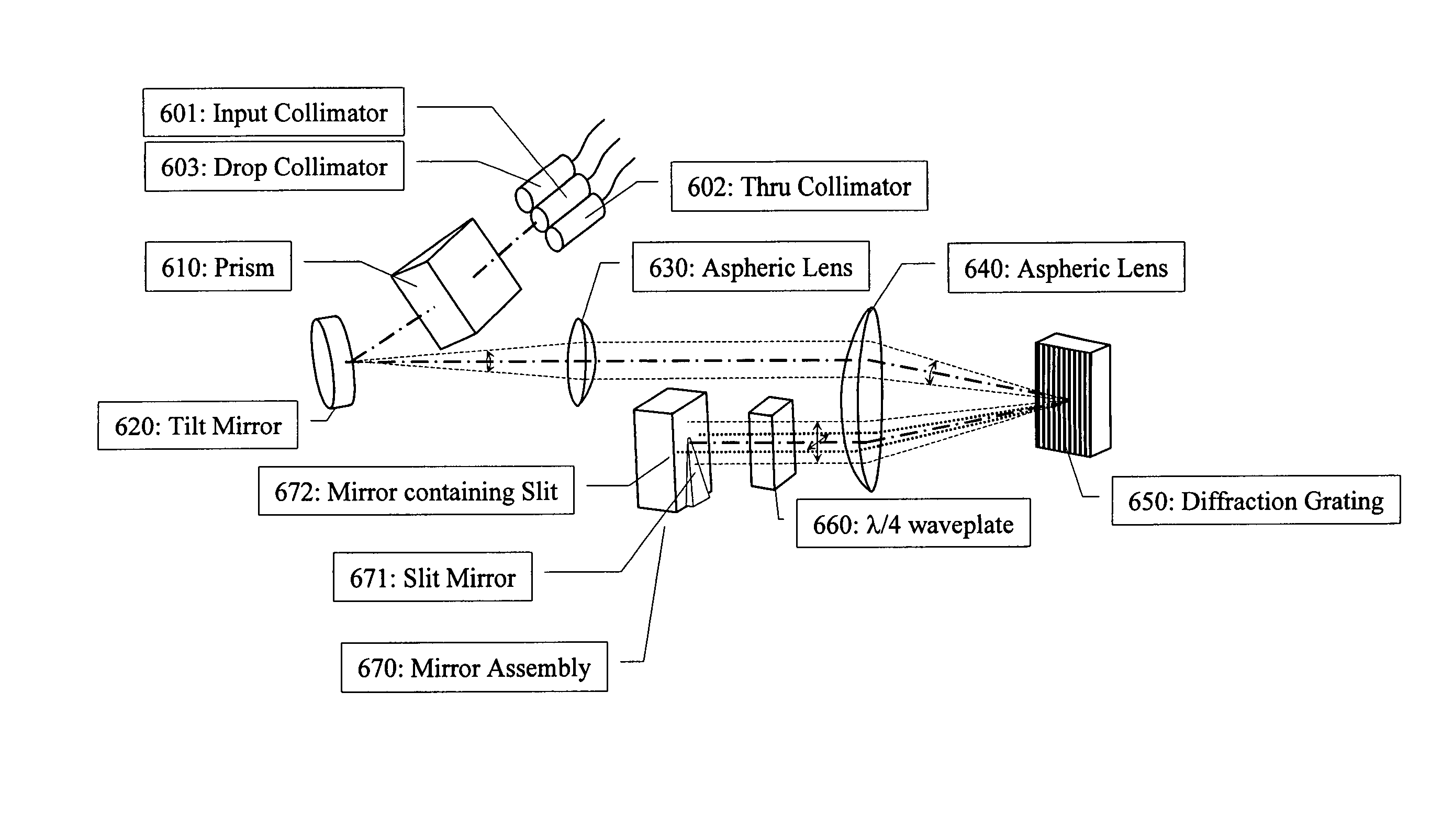
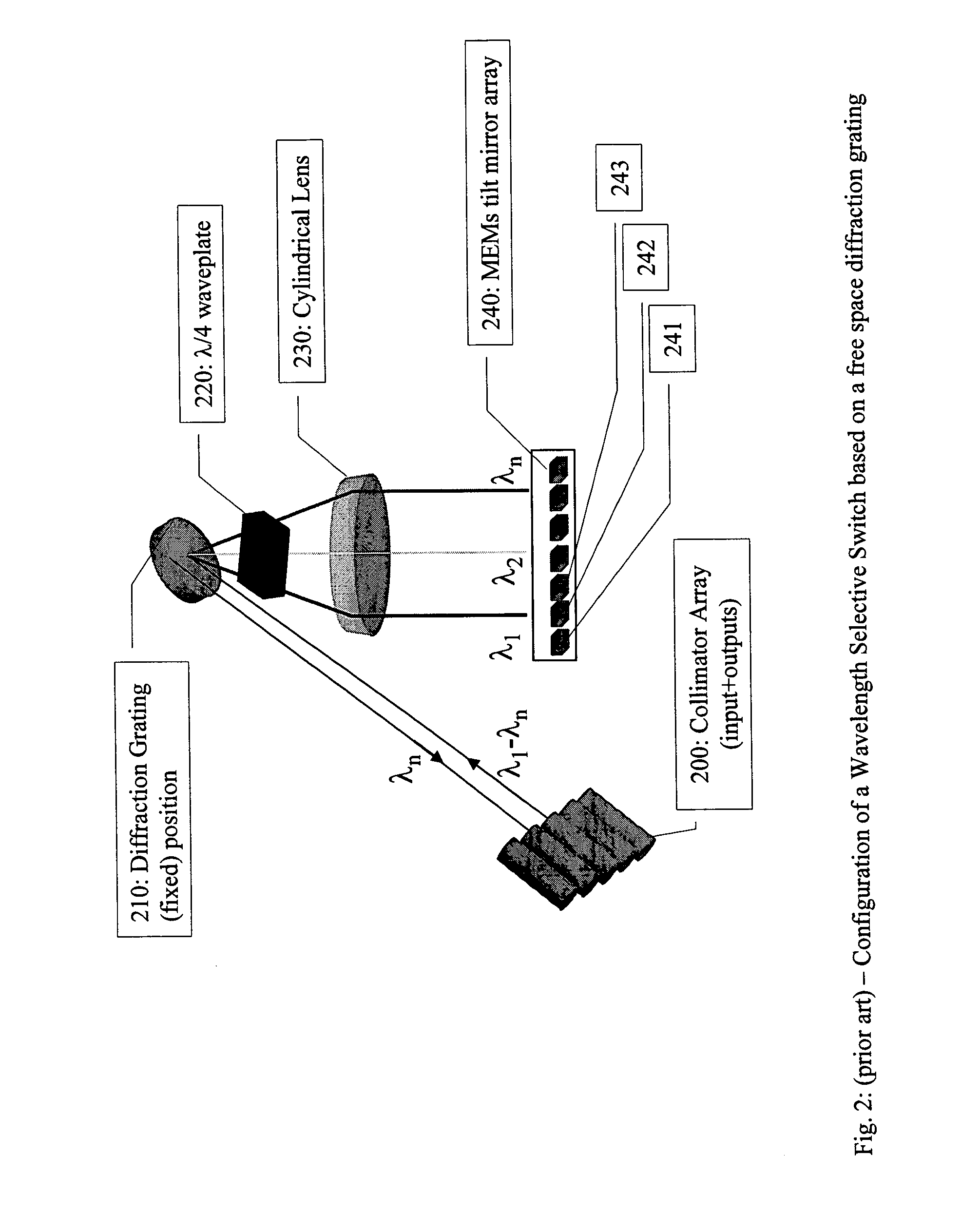
[0040]There are multiple technology platforms which have been used to demonstrate the functionality of a WSS, including free space optics with a diffraction grating (see U.S. Pat. Nos. 5,960,133, 6,097,859), free space optics with thin film filters (U.S. Pat. No. 6,631,222), and integrated photonic lightw...


PUM


Abstract

An optical spectral detection device utilizing free space optical beam propagation is provided. The device includes at least one optical fiber input, at least one opto-electronic detection device, an optical element having an actuator with at least one tilt axis, and a diffraction element having a surface thereon. The device also includes an optical beam transfer arrangement positioned between the optical element and the diffraction element such that tilt actuation of the optical element elicits a proportional change in an angle of incidence of the optical beam onto the diffraction element, wherein the center of rotation for the angular change is the surface of the diffraction element. The spectral properties of the optical beam that are detected are selected by selectively positioning the optical element about at least one of the tilt axes.

Description

STATEMENT OF RELATED APPLICATION[0001]This application claims the benefit of U.S. Provisional Application 60 / 564,904, filed Apr. 23, 2004, which is incorporated herein by reference in its entirety.FIELD OF THE INVENTION[0002]This invention generally pertains to wavelength division multiplexed optical communication systems, and more particularly to a means to direct light in a flexible manner, including the articles and means to construct such a system.BACKGROUND OF THE INVENTION[0003]There has been significant commercial interest in multiple wavelength WDM systems in recent years, hereafter referred to as Dense Wavelength Division Multiplexing (DWDM) systems. These systems leverage the capability of a single optical fiber to carry multiple wavelengths of light, a technique that effectively multiplies the bandwidth capacity of a given fiber by the number of wavelengths that can be transmitted. The demand for higher bandwidth communication systems has been driven by large increases in...

Claims


Application Information

Patent Timeline
Patent Type & Authority Patents(United States)
IPC IPC(8): G01J3/28
CPCG02B6/2706G02B6/2931G02B6/29313G02B6/2938G02B6/29395H04Q11/0005G02B6/2713H04Q2011/003G02B6/272G02B6/2793G02B6/3512G02B6/356H04J14/0205H04J14/0206H04J14/0208H04J14/021H04J14/0212H04J14/0213H04Q2011/0026
Inventor STRASSER, THOMAS ANDREWWAGENER, JEFFERSON L.KOEPPEN, CHRISTOPHER S.
Owner CHRISTOPHER S KOEPPEN
Why Eureka
Try Eureka