Technique for filter-enhanced clock synchronization

a clock synchronization and filter technology, applied in the field of computer and communication networks, can solve problems such as data loss, periodic line errors, data loss,

Inactive Publication Date: 2008-08-05
RPX CLEARINGHOUSE
View PDF2 Cites 3 Cited by
  • Summary
  • Abstract
  • Description
  • Claims
  • Application Information

AI Technical Summary

Benefits of technology

[0019]The present invention will now be described in more detail with reference to exemplary embodiments thereof as shown in the accompanying drawings. While the present invention is described below with reference to exemplary embodiments, it should be understood that the present invention is not limited thereto. Those of ordinary skill in the art having access to the teachings herein will recognize additional implementations, modifications, and embodiments, as well as other fields of use, which are within the scope of the present invention as disclosed and claimed herein, and with respect to which the present invention could be of significant utility.

Problems solved by technology

Two main performance degradation issues come into play when clocks at a transmitter and a receiver are not synchronized.
First, if the physical interfaces along a connection are not synchronized (i.e., not driven by a clocking signal of identical frequency), data can be lost due to buffer overflow or underflow, resulting in periodic line errors.
Second, imperfections in clock synchronization can lead to observable defects on an end service such as bit errors due to alignment jitter or frame slips.
In packet switched networks such as IP / Ethernet where essentially an asynchronous transmission service is provided, the synchronization needs of real-time applications are difficult to meet.
Unfortunately, the presence of transmission jitter affects the performance of the clock estimation / compensation process, making the transmitter clock appear faster or slower than it actually is, and ultimately, causing the propagation of some residual jitter to the receiver clock signal.
The presence of even a modest amount of jitter makes the clock recovery problem difficult.
One significant problem with existing PLL clock recovery circuits arises from the poor performance of their loop filters.
When a loop filter fails to effectively suppress the high frequency component of the detected clock error, the PLL will not acquire or maintain a true lock to the transmitter frequency.
However, in reality, even with both α1 and α2 optimized, a continual build-up of phase error can still be observed.

Method used


Image

  • Technique for filter-enhanced clock synchronization
  • Technique for filter-enhanced clock synchronization
  • Technique for filter-enhanced clock synchronization

Examples


Embodiment Construction

)

[0034]Referring to FIG. 4, there is shown a flow chart illustrating an exemplary method for filter-enhanced clock synchronization in accordance with the present invention.

[0035]The exemplary method starts in step 400.

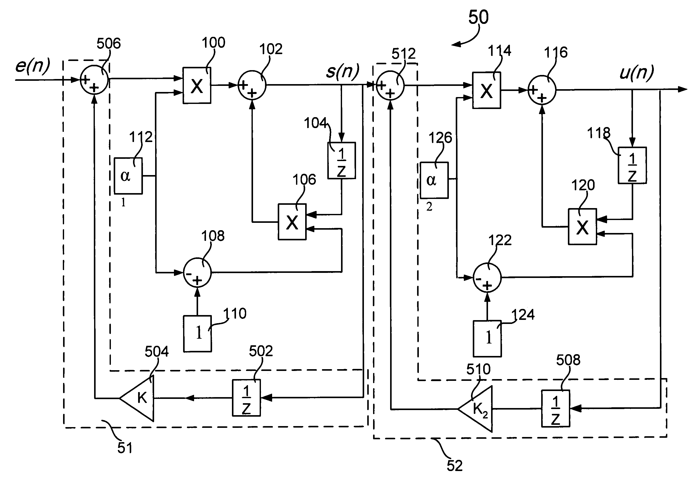
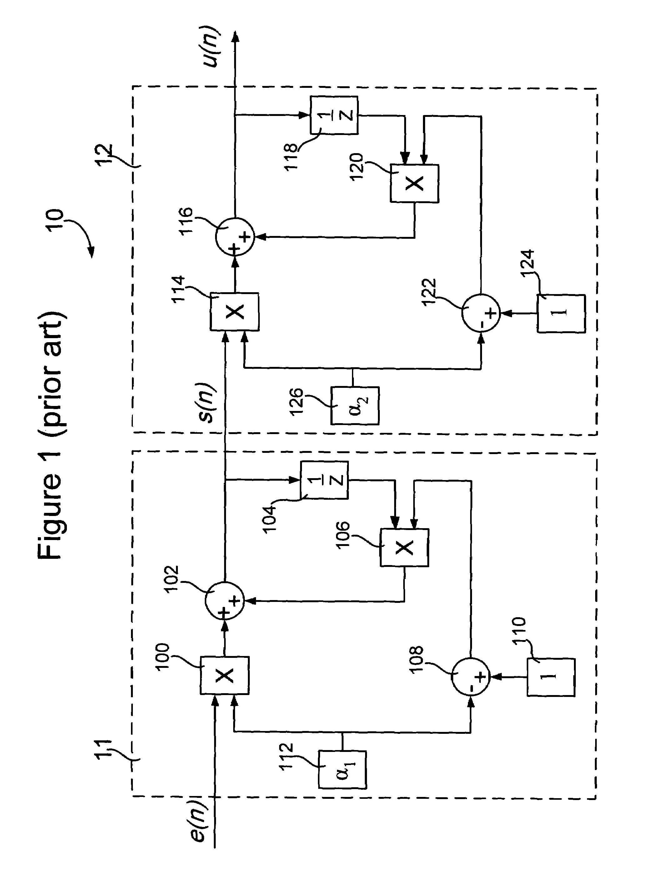
[0036]In step 402, a loop filter comprising a double EWMA filter may be provided in a phase-locked loop (PLL). The loop filter may be positioned between a phase detector and a voltage controlled oscillator (VCO) (or digitally controlled oscillator (DCO)). The loop filter, an example of which is shown in FIG. 5, may be based on the double EWMA filter shown in FIG. 1. In FIG. 5, the loop filter 50 comprises two cascaded EWMA filters. An EWMA filter is a circuit that can generate a smooth estimate of an input signal by applying a currently observed input signal to a previous estimate. As a result, the high frequency part of the input signal may be filtered out and its DC part may be retained.

[0037]In step 404, a first feedback loop 51 may be optionally coupled to the firs...


PUM


Abstract

A technique for filter-enhanced clock synchronization is disclosed. In one particular exemplary embodiment, the technique may be realized by/as a method for filter-enhanced clock synchronization. The method comprises subjecting a clock error signal to a first exponentially weighted moving average (EWMA) filter to generate a first output signal, where the first EWMA filter comprises a first gain element. And the method further comprises subjecting the first output signal to a second EWMA filter to generate a second output signal, where the second EWMA filter comprises a second gain element and the second EWMA filter is coupled with a feedback loop having a delay element and a summing junction.

Description

FIELD OF THE INVENTION[0001]The present invention relates generally to computer and communications networks and, more particularly, to a technique for filter-enhanced clock synchronization.BACKGROUND OF THE INVENTION[0002]Clock synchronization in a communications network is the means by which a clock signal is generated or derived and distributed through the network and its individual nodes for the purpose of ensuring synchronized network operation. Two main performance degradation issues come into play when clocks at a transmitter and a receiver are not synchronized. First, if the physical interfaces along a connection are not synchronized (i.e., not driven by a clocking signal of identical frequency), data can be lost due to buffer overflow or underflow, resulting in periodic line errors. Second, imperfections in clock synchronization can lead to observable defects on an end service such as bit errors due to alignment jitter or frame slips.[0003]In packet switched networks such as...

Claims


Application Information

Patent Timeline
Patent Type & Authority Patents(United States)
IPC IPC(8): H04B1/10
CPCH03L7/093H04J3/0632
Inventor WYRZYKOWSKA, ANETASOH, KAH MINGAWEYA, JAMESMONTUNO, DELFINOUELLETTE, MICHEL
Owner RPX CLEARINGHOUSE
Why Eureka
Try Eureka