Timing error reduction in QKD systems

a quantum key distribution and timing error technology, applied in the field of quantum cryptography, can solve the problems of undue amount of jitter in digital output, timing errors, etc., and achieve the effects of robust jitter reduction, reducing or eliminating timing errors, and reducing the jitter of fpga

Active Publication Date: 2008-08-05
MAGIQ TECH INC
View PDF11 Cites 6 Cited by
  • Summary
  • Abstract
  • Description
  • Claims
  • Application Information

AI Technical Summary

Benefits of technology

[0016]The present invention includes systems and methods for reducing or eliminating timing errors in a quantum key distribution (QKD) system (100) are disclosed. The QKD system has a pulse generator with retimer (PGRT) coupled to a field-programmable gate array (FPGA). The FPGA is programmed to operate as a timing generator (TG). The timing generator generates a digital timing signal (SF). While an FPGA has the desired degree of programmability for use in a QKD system, it also suffers from undue amounts of jitter in the digital output. Thus, the timing signal generated by the FPGA can cause timing errors. The present invention utilizes emitter-coupled logic (ECL) to reduce the timing jitter from the FPGA by coupling two ECL delays (ECL delay 1 and ECL delay 2) to the FPGA and to a retiming block (i.e., retimer RT), and by using an ECL logical AND gate to set the pulse width of the various synchronization signals sent to the various electrically controlled elements of the QKD system. An embodiment of the present invention includes a QKD system having multiple clock domains with individual clocks (CLK), phase-lock loops (PLLs), retiming circuits (RT) and timing generators (TG) for robust jitter reduction, and hence highly accurate QKD system timing.

Problems solved by technology

While an FPGA has the desired degree of programmability for use in a QKD system, it also suffers from undue amounts of jitter in the digital output.
Thus, the timing signal generated by the FPGA can cause timing errors.

Method used


Image

  • Timing error reduction in QKD systems
  • Timing error reduction in QKD systems
  • Timing error reduction in QKD systems

Examples


Embodiment Construction

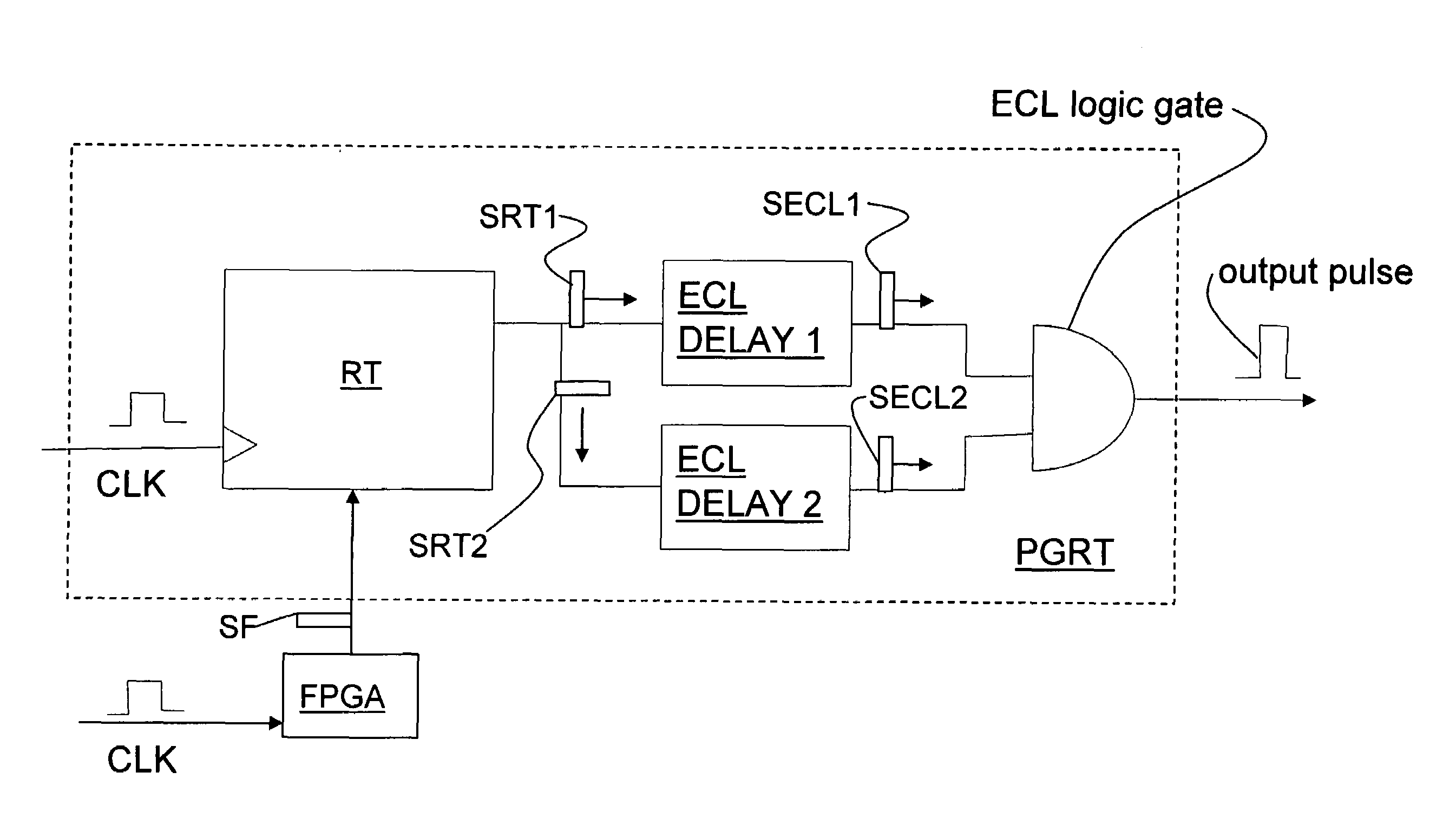
[0023]One approach to reducing timing jitter in a QKD system is to modify a retiming circuit previously used in the telecommunications industry to make it suitable for use in a QKD system. FIG. 2 is schematic diagram of a prior art retiming circuit 20 used in classical telecommunications. Circuit 20 includes a receiver RCV, a clock CLK, a retiming block RT, and a transmitter XMT. In circuit 20, the receiver RCV receives a weak electrical signal S20 from input line L1 that has timing jitter due to noise picked up along the transmission path.

[0024]If the transmitter XMT simply sent a copy of signal S20, it would pass on all the timing error in the form of a high transmitted jitter. The retiming block RT samples the receiver RCV at a time determined by its own low-jitter clock, and sends the transmitter XMT new information on the low jitter edge of the clock CLK. A D-type flip-flop is a commonly used in the circuit in retiming block RT to retime the signal. The use of the emitter coupl...


PUM


Abstract

Systems and methods for reducing or eliminating timing errors in a quantum key distribution (QKD) system (100) are disclosed. The QKD system has a pulse generator with retimer (PGRT) that includes a field-programmable gate array (FPGA) (or FPGA output) which is used as a timing generator (TG). While an FPGA has the desired degree of programmability for use in a QKD system, it also suffers from undue amounts of jitter in the digital output. The present invention utilizes emitter-coupled logic (ECL) to reduce the timing jitter from the FPGA by coupling two ECL delays (ECL delay 1 and ECL delay 2) to the FPGA and to retiming block, and by using an ECL logical AND gate to set the pulse width of the various synchronization signals. An embodiment of the present invention includes multiple clock domains having individual clocks (CLK), phase-lock loops (PLLs), retiming circuits (RT) and timing generators (TG) for robust jitter reduction and hence highly accurate QKD system timing.

Description

RELATED APPLICATIONS[0001]This application claims priority under 35 USC §119(e) from U.S. Provisional Patent Application Ser. No. 60 / 515,969, filed on Oct. 30, 2003.[0002]The present invention is related to U.S. Provisional Patent Application Ser. No. 60 / 601,906, filed on Aug. 26, 2004.FIELD OF THE INVENTION[0003]The present invention relates to quantum cryptography, and in particular relates to apparatus and methods for reducing timing errors in quantum key distribution (QKD) systems.BACKGROUND OF THE INVENTION[0004]Quantum key distribution involves establishing a key between a sender (“Alice”) and a receiver (“Bob”) by using weak (e.g., 0.1 photon on average) optical signals transmitted over a “quantum channel.” The security of the key distribution is based on the quantum mechanical principle that any measurement of a quantum system of an unknown state will modify its state. As a consequence, an eavesdropper (“Eve”) that attempts to intercept or otherwise measure the quantum signa...

Claims


Application Information

Patent Timeline
Patent Type & Authority Patents(United States)
IPC IPC(8): H04B10/00G06F1/04
CPCH04L9/0852H04L7/0008H04L7/0075H04L2209/34H04L7/02
Inventor VIG, HARRYTRIFONOV, ALEXEI
Owner MAGIQ TECH INC
Why Eureka
Try Eureka