Method for power consumption reduction in a limited-switch dynamic logic (LSDL) circuit

a technology of dynamic logic and power consumption reduction, applied in logic circuits, logic circuits characterised by logic functions, pulse techniques, etc., to achieve the effect of dramatically reducing power consumption in the clock distribution net and power consumption in the logic circui

Active Publication Date: 2008-08-12
MARVELL ASIA PTE LTD
View PDF18 Cites 12 Cited by
  • Summary
  • Abstract
  • Description
  • Claims
  • Application Information

AI Technical Summary

Benefits of technology

[0012]The dynamic logic gates are operated so that the clock signal is a voltage-asymmetric reduced swing version of the clock signal that controls the clocked devices in the dynamic logic gates. The voltage of the control signal during the evaluate phase of the clock signal is substantially closer to the midpoint of the power supply rail than the corresponding voltage of the clock signal, (generally at or below 75% of the power supply rail), but is substantially equal to the opposite power supply rail during the pre-charge phase of the clock signal. The asymmetric operation permits the logic gates to operate while reducing the power consumption in the clock distribution nets dramatically. The dynamic logic gates can also generally be designed without a summing node keeper circuit as in the above-incorporated patent application, since the reduced swing of the clock in the pre-charge direction will help obviate leakage, noise and charge sharing effects at the summing nodes of the dynamic logic gates. The clock distribution apparatus that operates the dynamic logic gates as described above comprises a level reducing element, generally a buffer or inverter, that receives a reduced voltage power supply input and transforms an input clock having a full voltage swing to the reduced voltage swing asymmetric clock described above.

Problems solved by technology

LSDL logic power consumption is dominated by clock power, in which the clock is typically consuming 70% of the total circuit power.

Method used


Image

  • Method for power consumption reduction in a limited-switch dynamic logic (LSDL) circuit
  • Method for power consumption reduction in a limited-switch dynamic logic (LSDL) circuit
  • Method for power consumption reduction in a limited-switch dynamic logic (LSDL) circuit

Examples


Embodiment Construction

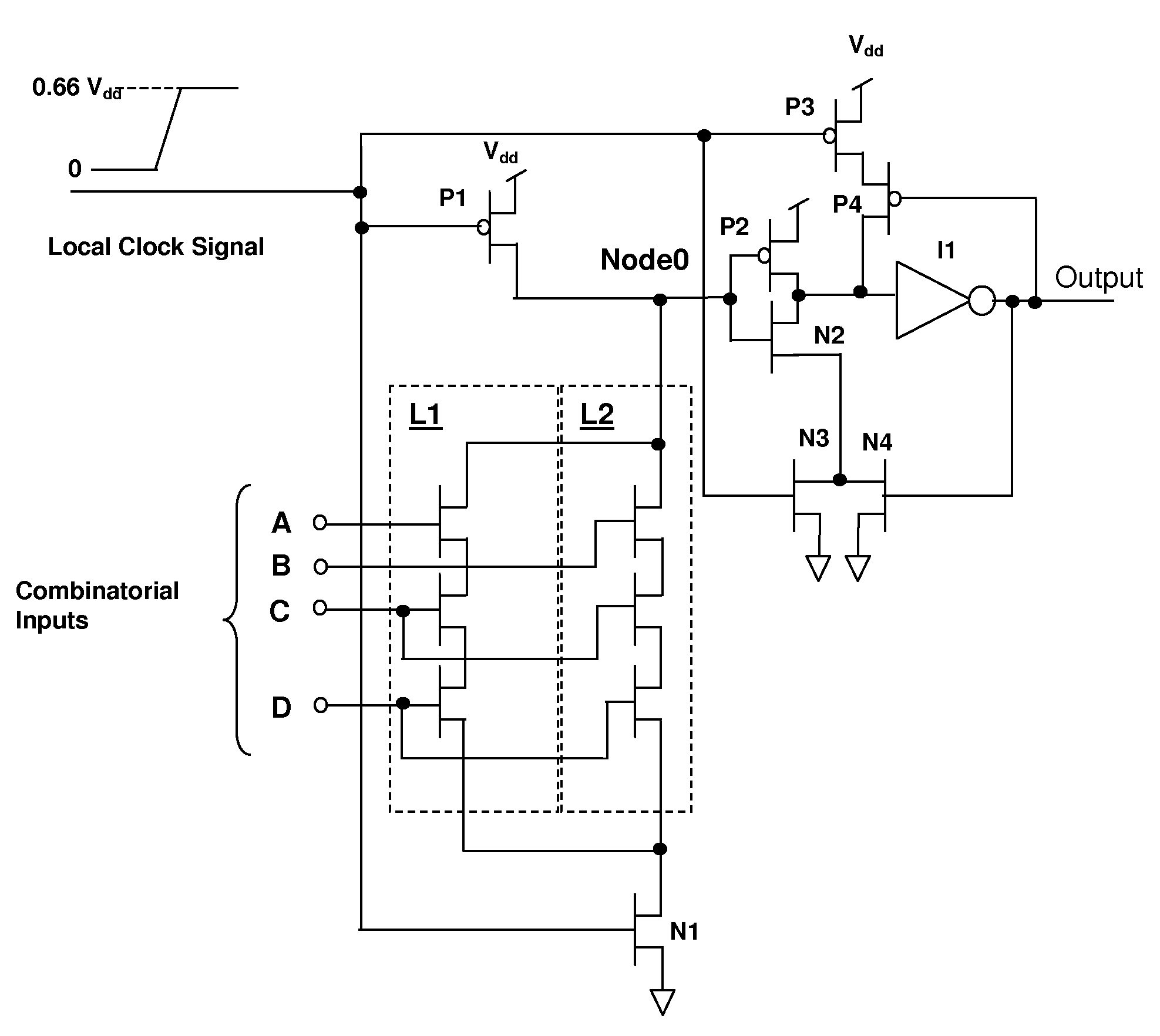
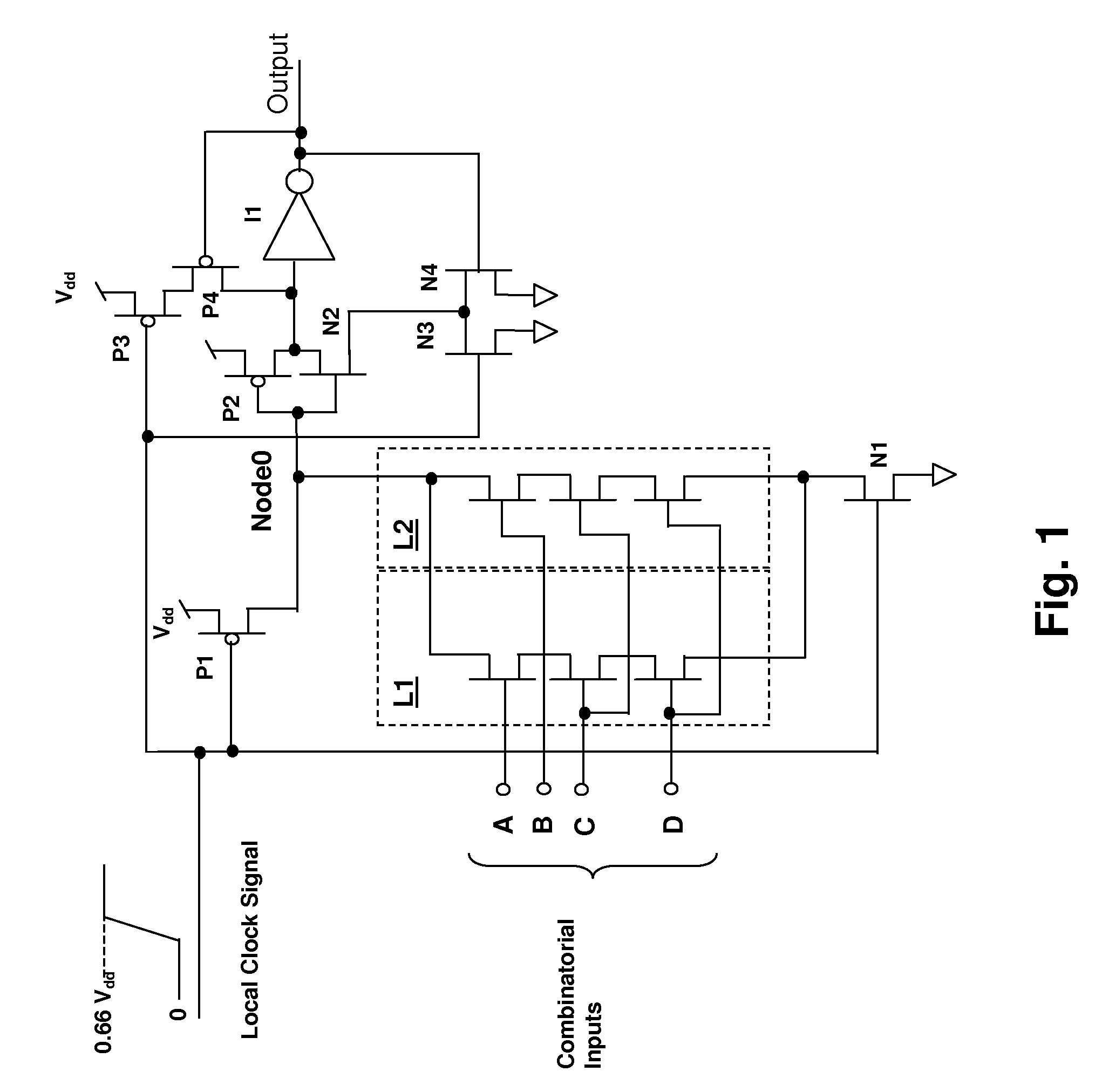
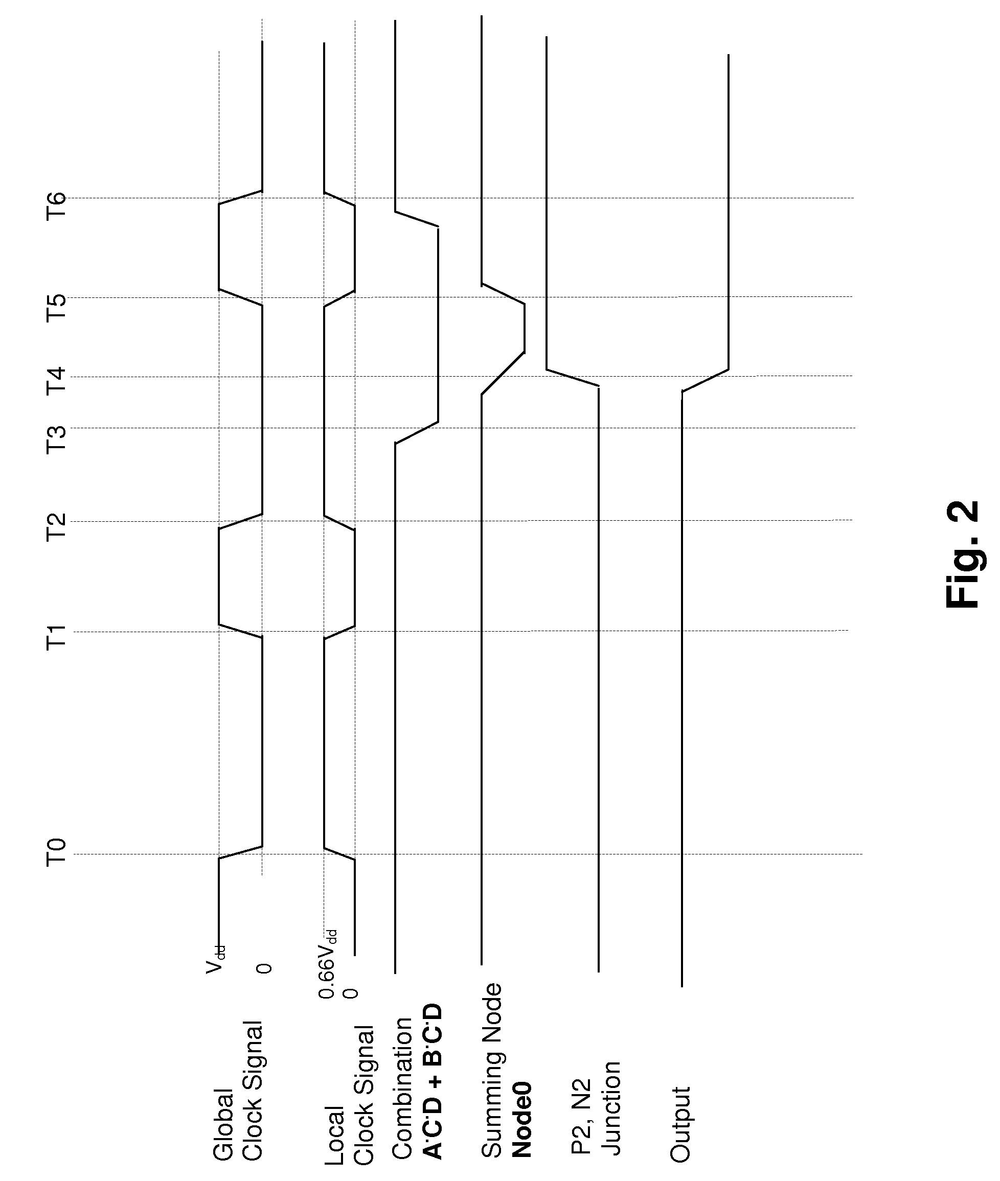
[0018]The present invention concerns a mechanism for reducing power consumption in dynamic logic circuits. Since clock power consumption is the predominant portion of the total consumption in large arrays of limited-switch dynamic logic, consuming on the order of 70 percent of the total power, the clocking of the present invention is altered from prior art clocking schemes to reduce the power associated with the clock signal distribution. The energy associated with each transition of the clock signal is CV2 / 2, where V is the change in voltage and where C is the effective capacitance and the power is directly proportional to the energy of each transition. C is the total effective capacitance on a clock line, which includes the lines themselves and all transistor gates connected to the clock signal, but is reduced somewhat from the static sum of the capacitances by the resistance of the lines. Since the clock power is proportional to the square of the clock voltage swing, any reductio...


PUM


Abstract

A method for power consumption reduction in a limited-switch dynamic logic (LSDL) circuit provides reduced power consumption by reducing clock power dissipation. By clocking LSDL gates with a clock signal having a reduced voltage swing in the evaluation phase, the LSDL gates are permitted to operate, while reducing the clock power consumption dramatically. Since clock power consumption dominates in LSDL circuits, the reduction in clock power dissipation results in a significant reduction in overall circuit power consumption. The reduced swing clock is produced at a plurality of local clock buffers by supplying the local clock buffers with an extra power supply rail that is switched onto the clock distribution lines by the local clock buffers in response to the full-swing evaluate phase clock received from the global clock distribution network by the local clock buffers.

Description

[0001]This invention was made with Government support under H98230-04-C-0920 IVY Grant (Zebra task4). THE GOVERNMENT HAS CERTAIN RIGHTS IN THIS INVENTION.CROSS-REFERENCE TO RELATED APPLICATION[0002]The present application is related to U.S. patent application “DYNAMIC LOGICAL CIRCUIT HAVING A PRE-CHARGE ELEMENT SEPARATELY CONTROLLED BY A VOLTAGE-ASYMMETRIC CLOCK”, Ser. No. 11 / 168,718, filed concurrently with this application and issued as U.S. Pat. No. 7,282,960 on Oct. 16, 2007, the applications having at least one common inventor and assigned to the same Assignee. The specification of the above-referenced application is incorporated herein by reference.BACKGROUND OF THE INVENTION[0003]1. Technical Field[0004]The present invention relates generally to dynamic logic circuits, and more particularly to a dynamic logical circuit having reduced power consumption by reducing the swing of the logic clock.[0005]2. Description of the Related Art[0006]Dynamic logic circuits are well known in...

Claims


Application Information

Patent Timeline
Patent Type & Authority Patents(United States)
IPC IPC(8): H03K19/20H03K19/094
CPCH03K19/0016
Inventor BELLUOMINI, WENDY ANNSAHA, ANIKET MUKUL
Owner MARVELL ASIA PTE LTD
Why Eureka
Try Eureka