Wear resistant center feed impact impeller

a technology of impact impeller and center feed, which is applied in the field of wear resistance center feed impact impeller, can solve the problems of delay in use of the apparatus, wear of components, and repair and replacement of components, and achieve the effect of reducing size and shape, and reducing wear

Inactive Publication Date: 2008-08-26
KENNAMETAL INC
View PDF17 Cites 6 Cited by
  • Summary
  • Abstract
  • Description
  • Claims
  • Application Information

AI Technical Summary

Benefits of technology

[0017]An impeller assembly for reducing wear is caused by a material flow. The impeller assembly includes one or more impeller tables, one or more impeller covers attached to the impeller tables, and brackets holding and interconnecting the tables and covers. The

Problems solved by technology

Regardless of the precise nature or function of an apparatus in which components are subjected to wear by a material flow, wear causes need for repair and replacement of components and delays in use of the apparatus while one or more worn components is identified, inspected, removed, and replaced.
Wear of components adds to the expense of maintaining and operating the apparatus.
Such delays, costs, and expenses are compounded if the apparatus in which wear occurs is located at a remote site.
The Hise Patents are instructive on the number and variety of components which may be included in an impact crusher and consequently exposed to wear during operation of an impact crusher.
It is significant that persistent wear occurs not just on anvils, which are designed to cooperate with other crusher components in crushing aggregate, but also on any other component of an impact crusher which may be exposed to the aggregate flow during operation of the crusher.
As a result of persistent wear caused by material flows, components of crushers must be replaced.
Replacement of components causes “down time” to repair, refit, and replace components.
Additional expenses are associat

Method used


Image

  • Wear resistant center feed impact impeller
  • Wear resistant center feed impact impeller
  • Wear resistant center feed impact impeller

Examples


Embodiment Construction

[0029]U.S. Pat. No. 5,954,282 to Britzke et al. issued on Sep. 21, 1999 is incorporated by reference herein in its entirety.

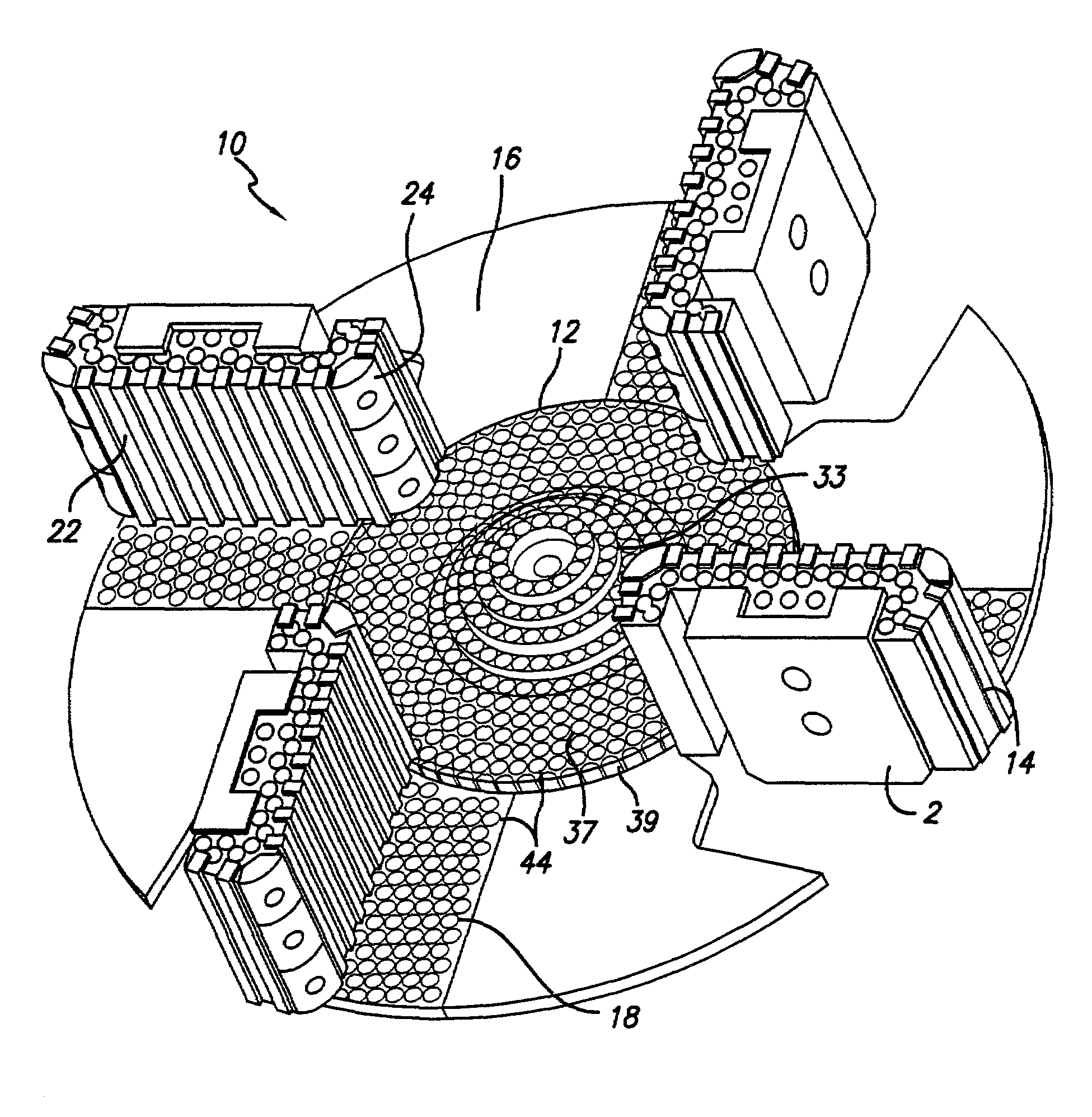
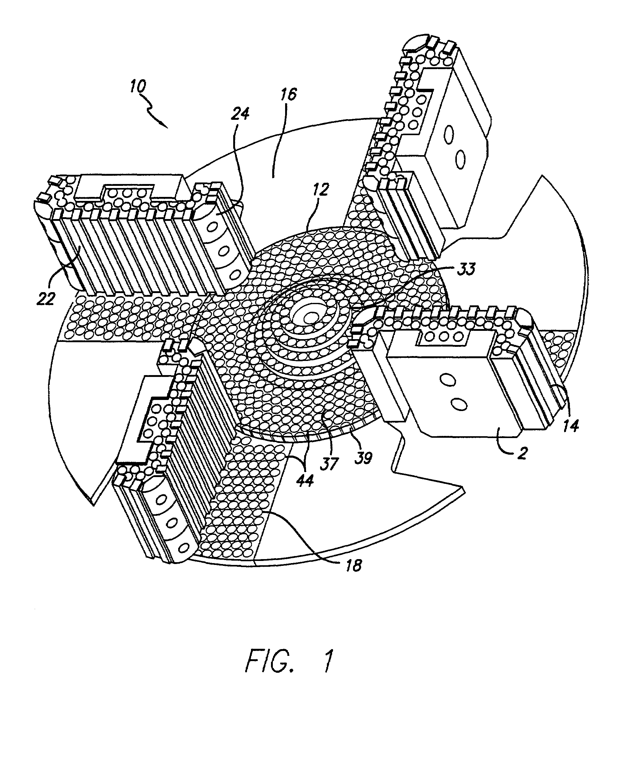
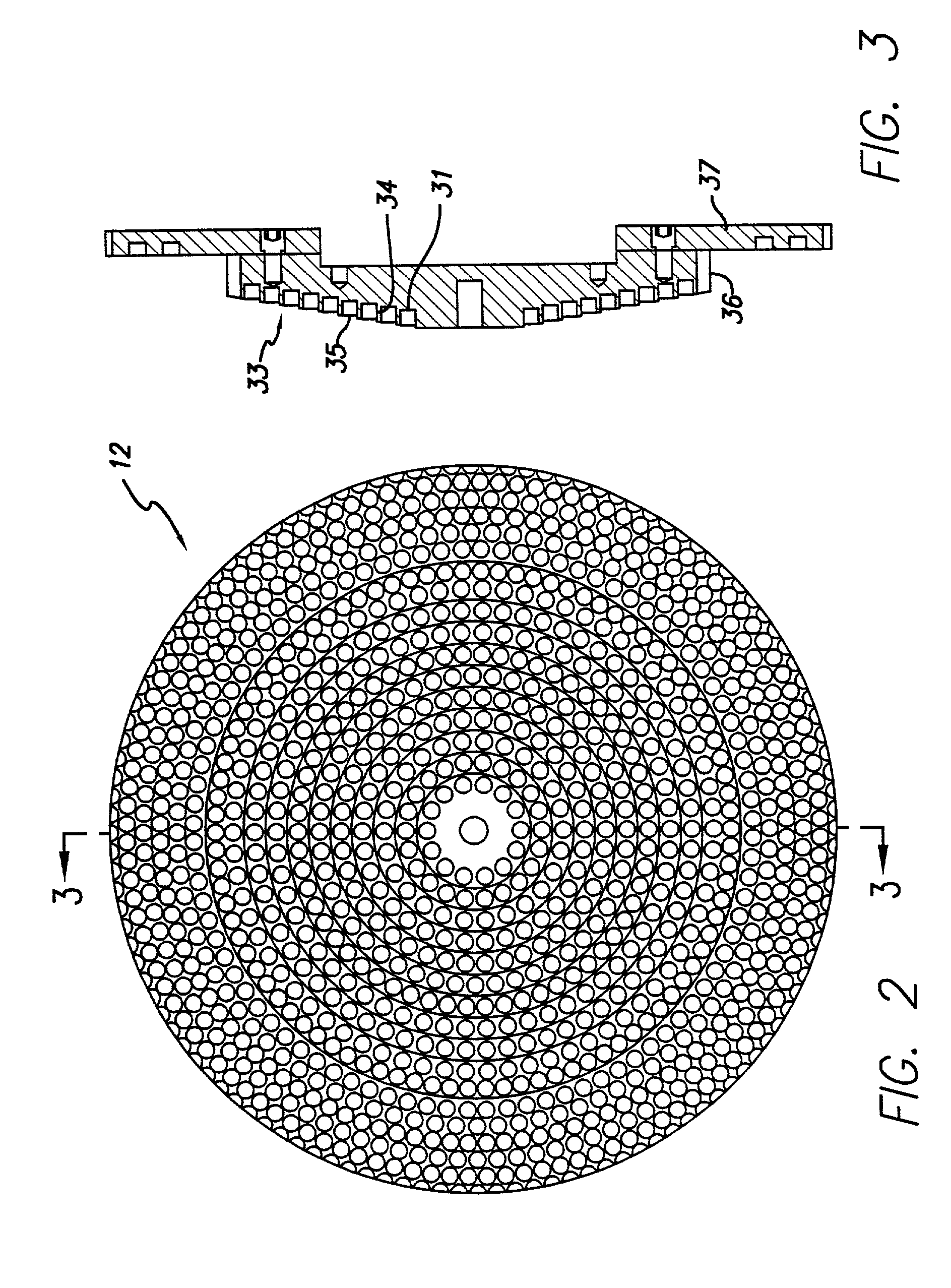
[0030]Referring initially to FIG. 1, a vertical impact crusher for reducing wear by a material flow, according to the present invention, is shown and generally designated 10. As shown, impact impeller assembly 10 includes rod inserts made from a hard material for reducing wear by a material flow. The impact impeller includes a central stepped feed body 12, impeller shoes 14, an impeller table 16, shoe liners 18 attached to impeller table 16, and brackets 20 holding and interconnecting table 16 and shoes 14.

[0031]The shoe liners 18 and shoes 14 are pre-assembled together and then may be attached to impeller table 16 to assist in projecting and directing an aggregate flow against, over, or around an anvil (not shown) of an impact crusher for crushing, fracturing, breaking up, and reducing in size and shape large aggregate into smaller sizes and shapes. Similarly,...


PUM


Abstract

The present invention is particularly, but not exclusively, useful for reducing wear of component parts of impact crushers caused by earth aggregate flows during operation of impact crushers. The present invention includes a stepped central feed cone that allows for cylindrical carbide rods to be press fit therein to reduce wear. The downward steps of the stepped cone urge material fed to the stepped cone outwardly to the table. The top surface of a first rod inserted into a first bore formed in the impeller housing extends a distance beyond the bottom of a second bore on the next step up. The first rod protects the housing material forming the second bore from being washed out by material flow. In one embodiment, the impeller shoes have a geometric shape that reduces excessive normal forces and accompanying high friction of the material against the shoe. The reduction in high friction significantly reduces the wear rate.

Description

FIELD OF THE INVENTION[0001]The present invention pertains to a plate for reducing wear of components of an impact crusher caused by an aggregate flow. The present invention is particularly, but not exclusively, useful for reducing wear of component parts of impact crushers caused by earth aggregate flows during operation of impact crushers.BACKGROUND OF THE INVENTION[0002]Regardless of the precise nature or function of an apparatus in which components are subjected to wear by a material flow, wear causes need for repair and replacement of components and delays in use of the apparatus while one or more worn components is identified, inspected, removed, and replaced. Wear of components adds to the expense of maintaining and operating the apparatus. Such delays, costs, and expenses are compounded if the apparatus in which wear occurs is located at a remote site.[0003]For example, a wide variety of impact crushers are used in commerce to reduce the size of larger earth materials to sma...

Claims


Application Information

Patent Timeline
IPC IPC(8): B02C19/00B02C13/18
CPCB02C13/1814B02C2013/28681
Inventor BRITZKE, ROBERT W.
Owner KENNAMETAL INC
Why Eureka
Try Eureka