Fuel injection valve for internal combustion engines and a method for hardening the said valve

a technology of internal combustion engines and fuel injection valves, which is applied in the direction of furnaces, heat treatment equipment, manufacturing tools, etc., can solve the problems that otherwise necessary complicated post-machining operations become unnecessary, and achieve the effects of reducing the notch effect in use, reducing erosion, and increasing vibration strength

Inactive Publication Date: 2008-09-02
ROBERT BOSCH GMBH
View PDF18 Cites 5 Cited by
  • Summary
  • Abstract
  • Description
  • Claims
  • Application Information

AI Technical Summary

Benefits of technology

[0006]The fuel injection valve for internal combustion engines according to the invention has the advantage over the prior art that the valve body is shape-and wear-resistant up to high temperatures and is thus suited for use at all operating points of an internal combustion engine. The valve body of the fuel injection valve comprises a high-alloy hot-work steel that has been hardened by a case-hardening or carburization process. Combining the high-alloy hot-work steel with a suitable carburization process favorably combines the advantages of both the material and the hardening process. A marked increase in the vibration strength of the high-alloy steel from a reduced notch effect in use, a reduction in erosion in the ensuing grinding machining at the function geometries, and a reduction in the necessary initial hardness of the valve body and hence improved machinability, as well as a reduction in the vulnerability to cavitation in the valve body, particularly in the region of the valve seat, are obtained.
[0010]The method according to the invention for hardening a valve body that is part of a fuel injection valve for internal combustion engines has the advantage that as a result of the treatment, the valve body has the requisite thermal strength for use in the combustion chamber of an internal combustion engine. To that end, the valve body is carburized in a gas atmosphere that contains a hydrocarbon and is then heat-treated at a temperature of approximately 900° C. in a vacuum, or at most at a pressure of 100 Pa. By the combination of these two method steps with a high-alloy hot-work steel, optimal hardening and wear resistance of the high-alloy hot-work steel can be achieved, so that this steel remains usable even at temperatures of the kind that occur under extreme loads in the combustion chamber of a self-igniting internal combustion engine.

Problems solved by technology

As a result of the carburization, an otherwise necessary complicated postmachining operation becomes unnecessary.

Method used


Image

  • Fuel injection valve for internal combustion engines and a method for hardening the said valve
  • Fuel injection valve for internal combustion engines and a method for hardening the said valve

Examples


Embodiment Construction

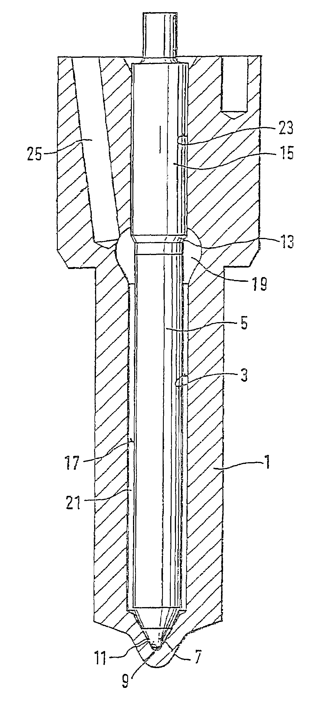
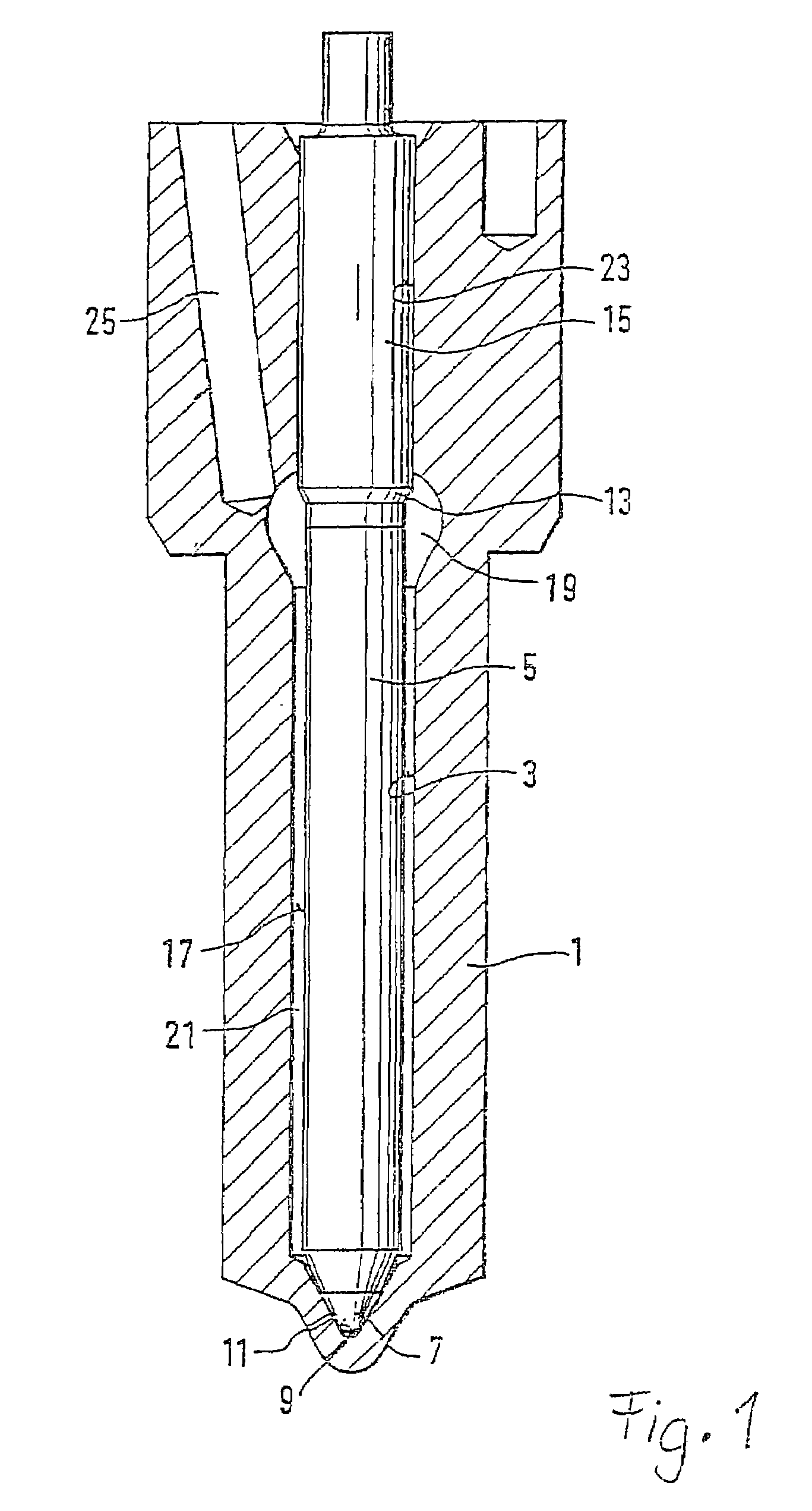
[0013]The fuel injection valve shown in FIG. 1 has a valve body 1, in which a valve needle 5 is disposed longitudinally displaceably in a bore 3. A substantially conical valve seat 9 is embodied on the end of the bore 3 toward the combustion chamber, and at least one injection opening 11 is embodied in the valve seat and connects the bore 3 with the combustion chamber of the engine. The valve needle 5 has a guide portion 15, with which it is sealingly guided in a guiding portion 23 of the bore 3. In the direction of the valve seat 9, the valve needle 5 narrows, forming a pressure shoulder 13, and changes over into a shaft portion 17 of reduced diameter. On the end of that portion, a substantially conical valve sealing face 7 is embodied which cooperates with the valve seat 9 and thus upon contact with the valve seat 9 closes the at least one injection opening 11 off from the bore 3.

[0014]At the level of the pressure shoulder 13, a pressure chamber 19 is embodied by a radial enlargem...


PUM

PropertyMeasurementUnit
temperatureaaaaaaaaaa
pressureaaaaaaaaaa
temperatureaaaaaaaaaa

Abstract

A fuel injection valve for internal combustion engines, having a valve body and at least one injection opening embodied in it, through which opening, controlled by a valve needle that cooperates with a valve seat embodied in the valve body, fuel can be injected into the combustion chamber of the engine. The valve body comprises a high-alloy hot-work steel, which has been hardened by a case-hardening process.

Description

CROSS-REFERENCE TO RELATED APPLICATIONS[0001]This application is a 35 USC 371 application of PCT / DE 02 / 02239 filed on Jun. 19, 2002.BACKGROUND OF THE INVENTION[0002]1. Field of the Invention[0003]This invention relates to an improved fuel injection valve and to a method of producing the valve.[0004]2. Description of the Prior Art[0005]From the prior art, various methods for hardening steel are known. The intent is to vary the wear resistance and durability of the material as well as its workability. One example is known as case-hardening or carburization, in which carbon is incorporated into the layers near the surface of the workpiece. One method in this respect is described in U.S. Pat. No. 4,836,864, for instance. Other possibilities are nitriding of steels, in which nitrogen is incorporated into the layers near the surface of the workpiece. In fuel injection valves as well, of the kind used preferably for self-igniting internal combustion engines and described for instance in Ge...

Claims


Application Information

Patent Timeline
Patent Type & Authority Patents(United States)
IPC IPC(8): C21D9/00C22C38/22C23C8/22F02M61/16
CPCC23C8/22F02M61/168F02M61/166F02M2200/9061
Inventor LIEDTKE, DIETERHOCH, ALFREDWOLF, FRANZ
Owner ROBERT BOSCH GMBH
Why Eureka
Try Eureka