Phase lock loop RF modulator system

a phase lock loop and modulator technology, applied in the direction of pulse automatic control, angle modulation details, electrical apparatus, etc., can solve the problems of increasing the bandwidth of fractional-n pll, reducing the modulation quality, and requiring a lot of power, so as to achieve less complex and less expensive

Active Publication Date: 2008-09-02
ANALOG DEVICES INC
View PDF15 Cites 10 Cited by
  • Summary
  • Abstract
  • Description
  • Claims
  • Application Information

AI Technical Summary

Benefits of technology

[0011]It is a further object of this invention to provide such an RF modulator system which is less complex.
[0012]It is a further object of this invention to provide such an RF modulator system which is less expensive.
[0015]It is a further object of this invention to provide such an RF modulator system which eliminates the need for offline calibration.
[0020]It is a further object of this invention to provide such an RF modulator system which is able to measure and reduce the gain mismatch between the modulation ports and employ pre-emphasis.
[0022]The result is a system able to measure the gain of a first modulation port and a second modulation port of the system and then modify the gain of one of those ports in feedback to reduce the gain mismatch between the first and second modulation ports and that has the characteristics of both a high bandwidth filter to accommodate high data rates and a low bandwidth filter to remove unwanted noise.
[0026]This invention also features a phase lock loop RF modulator system including a phase lock loop circuit. The phase lock loop circuit includes a phase detector circuit responsive to an input reference signal and a feedback signal, an oscillator circuit responsive to the phase detector circuit for providing an output signal, a forward path from the phase detector circuit to the oscillator circuit, and a feedback path from the oscillator circuit to the phase detector circuit. The system also includes a first modulation port coupled to the feedback path, a second modulation port coupled to the forward path, a gain mismatch detection circuit responsive to modulation data and phase error between the reference signal and the feedback signal for providing an indicator output signal that represents the gain mismatch between the first modulation port and the second modulation port, and a tuning circuit responsive to the indicator output signal for modifying at least one parameter associated with one or more parameters of the first modulation port, the second modulation port, and the phase lock loop circuit such that the gain mismatch is reduced.

Problems solved by technology

These systems are fairly complicated, expensive, require a lot of power, and utilize significant die area.
However, when a conventional fractional-N PLL is utilized at higher data rates, the noise, e.g., quantization noise, introduced by the increased bandwidth of the fractional-N PLL degrades modulation quality.
However, the gain associated with second modulation port is often not as expected due to manufacturing processes, temperature variations, supply voltage variations, and the like, of the various components of the PLL.
Hence, the gain of the second modulation port will typically not match the gain of the first modulation port, causing the PLL loop gain to vary significantly resulting in system malfunctioning.
However, these conventional systems provide no feedback and cannot determine if the gain adjustment is compensated as required.
The systems require at least a one time calibration that requires taking the system offline which is cumbersome and expensive.
The drawback of this design is the need for RF phase sampling and quadrature, which is expensive and complicated.

Method used


Image

  • Phase lock loop RF modulator system
  • Phase lock loop RF modulator system
  • Phase lock loop RF modulator system

Examples


Embodiment Construction

[0050]Aside from the preferred embodiment or embodiments disclosed below, this invention is capable of other embodiments and of being practiced or being carried out in various ways. Thus, it is to be understood that the invention is not limited in its application to the details of construction and the arrangements of components set forth in the following description or illustrated in the drawings. If only one embodiment is described herein, the claims hereof are not to be limited to that embodiment. Moreover, the claims hereof are not to be read restrictively unless there is clear and convincing evidence manifesting a certain exclusion, restriction, or disclaimer.

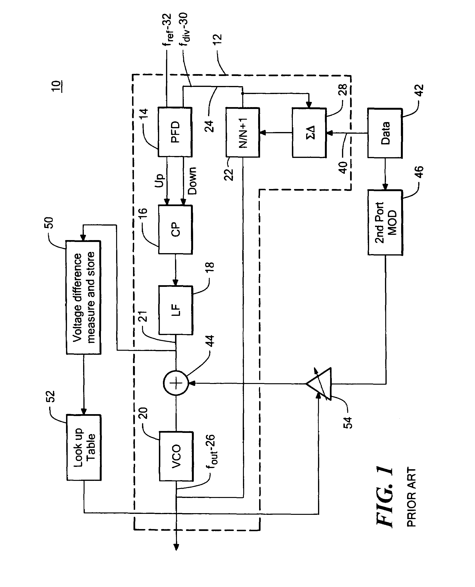
[0051]As discussed in the Background section above, conventional PLL RF modulator system 10, FIG. 1 typically includes fractional-N PLL circuit 12. Circuit 12 typically includes phase / frequency detector 14, charge pump 16, loop filter 18, voltage controlled oscillator (VCO) 20 and N-divider circuit 22 in feedback loop 24 wh...


PUM


Abstract

A phase lock loop RF modulator system including a phase lock loop circuit having a phase detector circuit responsive to an input reference signal and a feedback signal, an oscillator circuit responsive to the phase detector circuit for providing an output signal, a forward path from the phase detector circuit to the oscillator circuit, and a feedback path from the oscillator circuit to the phase detector circuit. The system also includes a first modulation port coupled to the feedback path, a second modulation port coupled to the forward path, and a gain mismatch detection circuit responsive to modulation data and a phase error between the reference signal and the feedback signal for providing an indicator output signal that represents the gain mismatch between the first modulation port and the second modulation port.

Description

RELATED APPLICATIONS[0001]This application claims benefit of U.S. Provisional Application Ser. No. 60 / 737,600 filed Nov. 17, 2005, incorporated by reference herein.FIELD OF THE INVENTION[0002]This invention relates generally to phase lock loop (PLL) RF modulator systems and more particularly to an improved two port PLL RF modulator system with gain matching between the modulation ports.BACKGROUND OF THE INVENTION[0003]Conventional IQ modulator systems used to generate phase / frequency modulated data typically include a Cartesian up converter that employs a local oscillator in the form of a PLL. These systems typically require at least an RF quadrature generator, two RF mixers and two digital-to-analog converters. These systems are fairly complicated, expensive, require a lot of power, and utilize significant die area.[0004]A more efficient way to generate modulation signals utilizes the fine phase / frequency control available with a fractional-N PLL. However, when a conventional fract...

Claims


Application Information

Patent Timeline
Patent Type & Authority Patents(United States)
IPC IPC(8): H03C3/06
CPCH03C3/0925H03C3/0933H03L7/1976H03C3/095H03C3/0991H03C3/0941
Inventor O'SULLIVAN, CORMAC E.LYDEN, COLINSHANAN, HYMAN N.
Owner ANALOG DEVICES INC
Why Eureka
Try Eureka