
Dispersion-free, automatically phase-matched, and broad spectral-band femtosecond autocorrelation technique

a femtosecond, autocorrelation technology, applied in the field of optical autocorrelation technique, can solve the problems of limiting the spectral bandwidth that can be characterized simultaneously, no crystal is known to work efficiently for wavelengths shorter than 400 nm, and the autocorrelation technique is straightforward. , to achieve the effect of eliminating background offset, avoiding material dispersion, and high efficiency

Inactive Publication Date: 2008-09-02
UNIVERSITY OF ROCHESTER
View PDF1 Cites 4 Cited by
  • Summary
  • Abstract
  • Description
  • Claims
  • Application Information

AI Technical Summary

Benefits of technology

[0010]This surface SHG autocorrelation scheme provides a number of unique advantages. First, since SHG is generated from a few top surface layers, the phase-matching condition is automatically fulfilled. Second, the measurement is virtually dispersion free since only a few atomic layers are involved, and the reflected signal is collected (avoiding materials dispersion to transmit light). Third, SHG can be generated from a metal surface over an extremely broad wavelength range. In principle, the SHG signal can be produced from far infrared to deep ultraviolet, up to the plasma frequency of the metal used (e.g., about 10 eV for gold). This broad spectral bandwidth property is the most significant advantage over other existing techniques and it promises a unique way to characterize ultra-broad-band short pulses that may not be accomplished otherwise.

Problems solved by technology

The autocorrelation technique, although straightforward, has a number of disadvantages for characterizing femtosecond pulses.
The most significant disadvantage originates from the phase-matching requirement, which limits the spectral bandwidth that can be characterized simultaneously.
In fact, no crystal is known to work efficiently for wavelengths shorter than 400 nm.
Furthermore, dispersion in a nonlinear crystal itself introduces errors in ultrashort pulse measurements.
Moreover, nonlinear crystals are usually quite expensive, especially those made for special purposes (e.g., thin crystals needed for reducing dispersion).
This feature may restrict the suitability of such a technique when pulses have a super-broad spectrum such as those produced from photonic-crystal fibers.
This dispersion still poses a less desirable effect in ultrashort pulse measurements.

Method used


Image

  • Dispersion-free, automatically phase-matched, and broad spectral-band femtosecond autocorrelation technique
  • Dispersion-free, automatically phase-matched, and broad spectral-band femtosecond autocorrelation technique
  • Dispersion-free, automatically phase-matched, and broad spectral-band femtosecond autocorrelation technique

Examples


Embodiment Construction

[0024]Two preferred embodiments of the present invention will be set forth in detail with reference to the drawings, in which like reference numerals refer to like elements throughout.

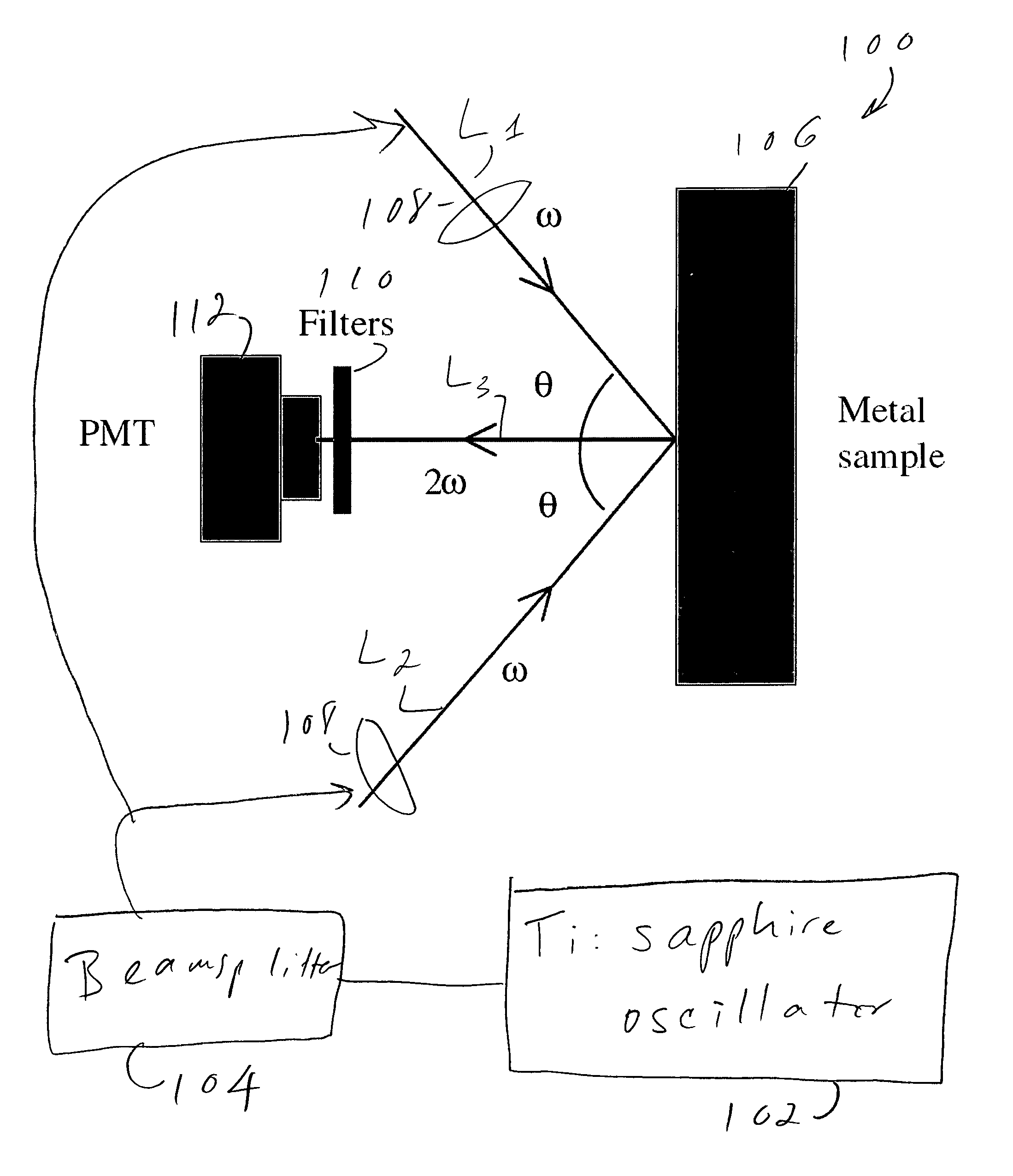
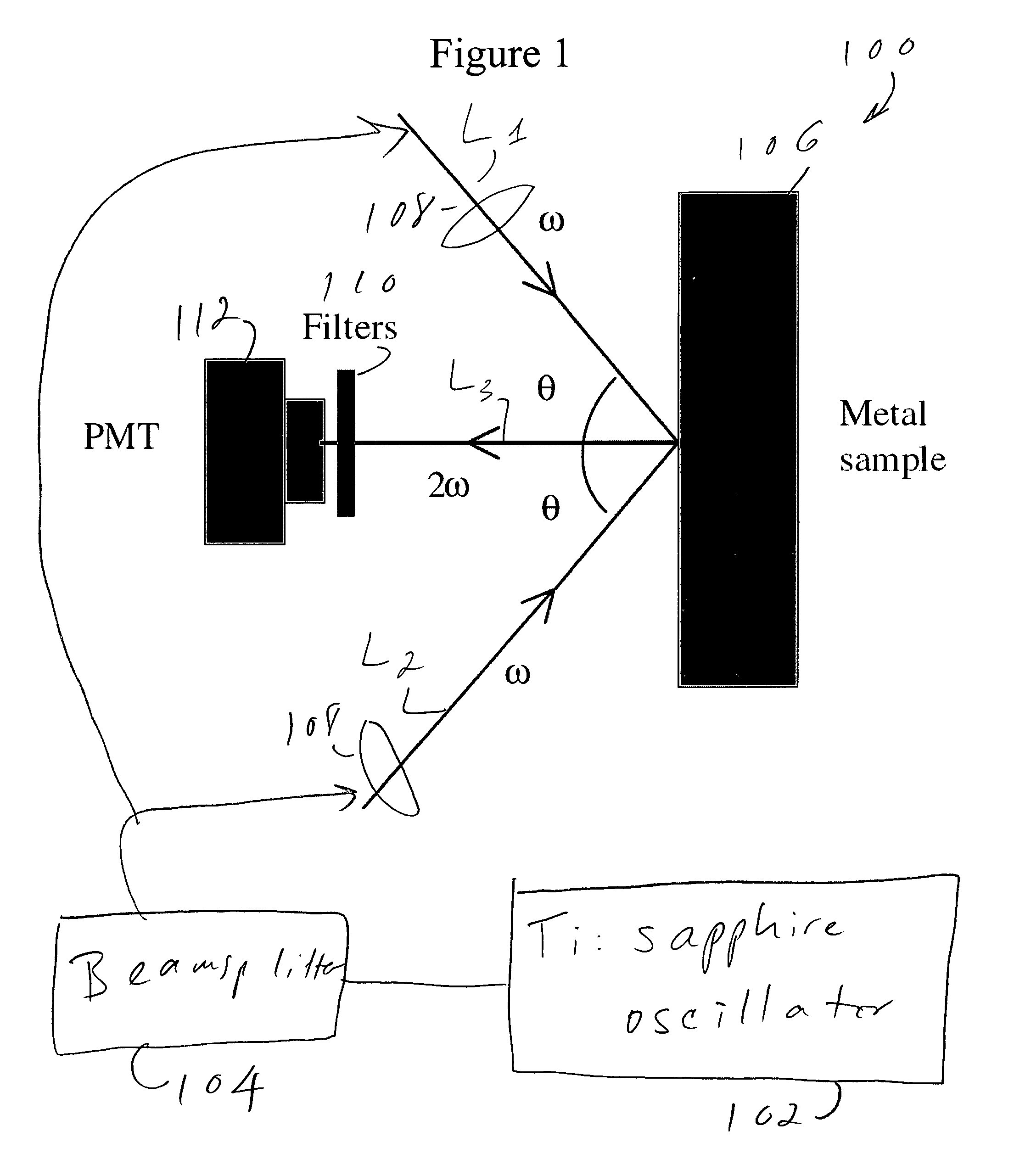
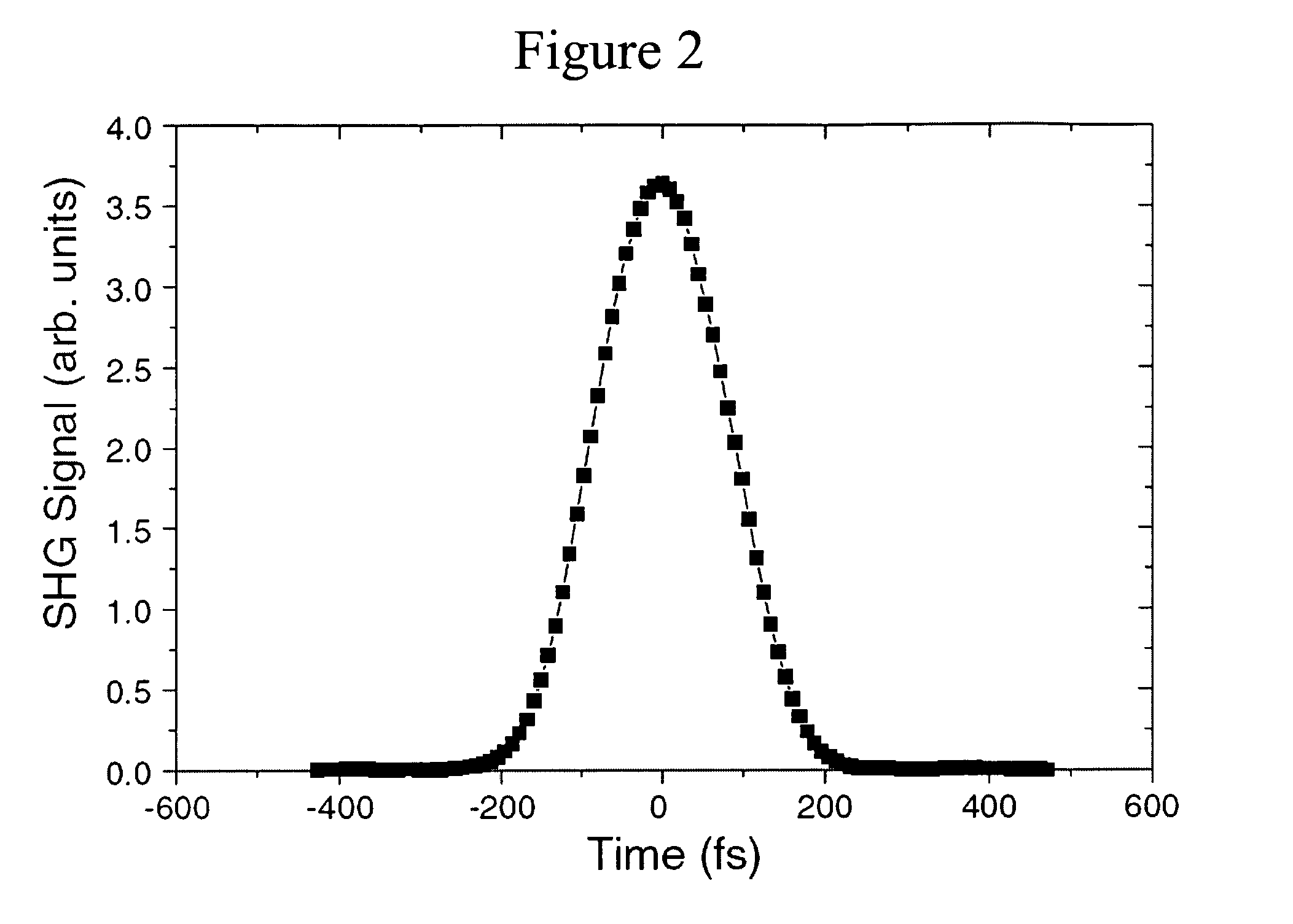
[0025]A first preferred embodiment will be described with reference to FIGS. 1-4. The hardware setup according to the first preferred embodiment is shown in FIG. 1 as 100. The first preferred embodiment 100 uses a femtosecond Ti:sapphire oscillator 102 running at 800 nm central wavelength with a repetition rate of 94.3 MHz. The beam from the oscillator is split into two pulse trains L1, L2 using a 50 / 50 beam splitter 104 such that each path carries nearly half the average power. The two beams L1, L2 are p polarized and focused onto the metal sample 106 with two identical lenses 108. The second harmonic L3, generated through two-overlapping beams at the sample surface, is emitted in the normal direction. A photomultiplier tube (PMT) 112 is used to detect the surface SHG. Filters 110 transmitting 400 nm ...


PUM

PropertyMeasurementUnit
wavelength rangeaaaaaaaaaa
wavelengthsaaaaaaaaaa
central wavelengthaaaaaaaaaa

Abstract

Two optical signals are autocorrelated by causing them to be incident on a metal surface, where they generate a second (or higher) harmonic signal. The resulting harmonic signal is detected by a photomultiplier tube or the like. The harmonic signal generation on the metal surface is phase-matched and dispersion free and can be performed over a wide range of wavelengths.

Description

REFERENCE TO RELATED APPLICATION[0001]The present application claims the benefit of U.S. Provisional Patent Application No. 60 / 675,918, filed Apr. 29, 2005, whose disclosure is hereby incorporated by reference in its entirety into the present disclosure.STATEMENT OF GOVERNMENT INTEREST[0002]The work leading to the present invention was supported by DARPA under Award No. W911INF-04-1-0199. The government has certain rights in the invention.FIELD OF THE INVENTION[0003]The present invention is directed to an optical autocorrelation technique and more particularly to such a technique using second harmonic generation (SHG) on a metal surface.DESCRIPTION OF RELATED ART[0004]Temporal characterization of sub-picosecond laser pulses can be most conveniently achieved by using optical auto- or cross-correlation techniques. More advanced measurements, such as those that can record both intensity and phase information, are also based on the simple correlation platform.[0005]Traditional optical a...

Claims


Application Information

Patent Timeline
Patent Type & Authority Patents(United States)
IPC IPC(8): G01N21/25
CPCG01J11/00
Inventor GUO, CHUNLEI
Owner UNIVERSITY OF ROCHESTER
Learn More