Cellular stirrups and ties for structural members

a structural member and cellular technology, applied in the direction of structural elements, pillars, building components, etc., can solve the problems of high cost, high steel requirement, excessive weight, etc., and achieve the effect of reducing the difficulty of spiraling during the reinforcement of the structural member

Inactive Publication Date: 2008-09-09
KONSTANTINIDIS APOSTOLOS
View PDF11 Cites 25 Cited by
  • Summary
  • Abstract
  • Description
  • Claims
  • Application Information

AI Technical Summary

Benefits of technology

[0014]According to the present invention, the stirrup or tie of a concrete structural member consists of a load bearing element for the fixing of the longitudinal rebars and for the undertaking of the tensile forces which develop during the loading of the structural member. The bearing element consists of at least one cell of closed shape so that the flow of the tensile stresses developed in the cross-section is closed and it is not diffused to the concrete. The loa

Problems solved by technology

The disadvantages of these stirrups and ties are: a) the mechanical anchorage point is very delicate and is a point of probable defective construction, b) the anchorage mechanism confines the use of high-grade steel, i.e. of strength 1200 MPa, in this type of stirrups and ties and the result is that much steel is required with great weight and high cost, c) and there is a need for relatively careful

Method used


Image

  • Cellular stirrups and ties for structural members
  • Cellular stirrups and ties for structural members
  • Cellular stirrups and ties for structural members

Examples


Embodiment Construction

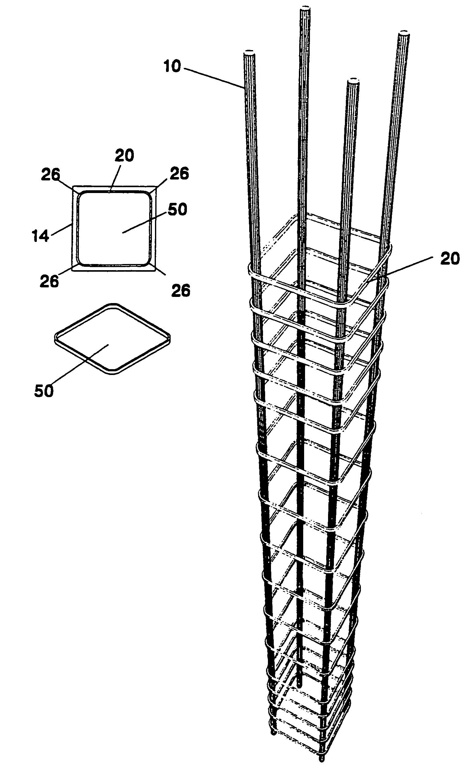
[0064]FIG. 3 resents a stirrup within the framework 14. The stirrup consists of a load-bearing element 20 which is a rectangular ring and closed cell 50 having an inner periphery and an outer periphery. At the corners of the ring 50, there is a provision of special places 26 for receiving the rebars 10. These places may be formed like the shape of the perimeter of the rebars 10, so that the rebars are received within the inner periphery of the dosed cell and abut against it.

[0065]During the loading of the structural element and the rebars 10, axial tensile forces are created in the cross-section of the bearing element 20. Because of the closed cellular shape of the bearing element, the axial tensile forces are not transferred to the concrete, which surrounds the reinforcement.

[0066]The load-bearing element 20 of the stirrup of FIG. 3 has a continuous cross-section and thus there are no free ends. In this way anchoring of the stirrup is completely avoided. The dosed cellular shape ha...


PUM


Abstract

The present invention refers to stirrups and ties for structural members. Such stirrups and ties are used in all the structural members like columns, beams, slabs, footings, piles, chainages, lintels etc. The invention refers also to a method of reinforcement of structural members and to the structural members themselves. According to the invention the stirrup or tie consists of a load-bearing element for the fixing of the longitudinal rebars and for the undertaking of the tensile forces which develop during the loading of the structural members. The load bearing element consists of at least one cell of closed shape so that the flow of the tensile stresses developed in the cross section is closed and the stresses are not diffused to the concrete. The load bearing element of the stirrup or tie in accordance to the invention has a continuous cross section and thus there are no free ends as in the known stirrups. In this way anchoring of the stirrups or ties is completely avoided. The closed cellular shape has no discontinuation and may be simple, for example, rectangular, circular, T-shaped, I-shaped, etc. or complete, for example, square with inscribed rectangular, circular with inscribed per square etc.

Description

BACKGROUND OF THE INVENTION[0001]1. Field of the Invention[0002]The present invention refers to stirrups and ties for structural members. Such stirrups and ties are used in all the structural members like columns, beams, slabs, footings, piles, chainages, lintels e.t.c. The invention refers also to a method of reinforcement of structural members and to the structural members themselves.[0003]2. Description of the Current Art[0004]It is known that stirrups and ties constitute one of the most critical factors of strength of concrete structural members because they undertake the tensile forces, which cannot be carried by the concrete itself. These tensile forces are due to the shear forces, which load the structural member, and / or to the internal pressure which is created when the structural member is subjected to strong compressive loads.[0005]The usual stirrups and ties of the concrete structural members consist of steel bars of grade 220 MPa up to grade 500 MPa with circular cross-s...

Claims


Application Information

Patent Timeline
IPC IPC(8): E04C3/30E04C5/06E04C5/18
CPCE04C5/0604E04C5/208E04C5/0618
Inventor KONSTANTINIDIS, APOSTOLOS
Owner KONSTANTINIDIS APOSTOLOS
Why Eureka
Try Eureka