Method and device for declogging filter

a filter and filter block technology, applied in combination devices, filtration of dispersed particles, fluidised-bed furnaces, etc., can solve the problems of increasing pressure drop, complex use and maintenance, and filter blockage during plant operation

Active Publication Date: 2008-09-09
AREVA NP SAS
View PDF14 Cites 13 Cited by
  • Summary
  • Abstract
  • Description
  • Claims
  • Application Information

AI Technical Summary

Benefits of technology

[0023]The aim of the invention is therefore to provide a method of declogging at least one filter of a plant for manufacturing uranium oxide from uranium hexafluoride, comprising a reactor in which gaseous hexafluoride UF6 and steam are injected, uranium oxyfluoride UO2F2 in powder form and gaseous hydrofluoric acid HF are formed, uranium oxyfluoride UO2F2 conveyed by gases containing gaseous hydrofluoric acid HF is separated at the outlet of the reactor, in at least one filtration unit arranged on an outlet part of the reactor, comprising at least one filter having a tubular filtration wall arranged with its axis vertical, and hydrofluoric acid is evacuated to the outside of the reactor, the declogging of the filter consisting in separating, from the wall of the filter, uranium oxyfluoride particles deposited, by a stream of inert gas such as nitrogen, injected into the filter, in a counter-currentwise direction to the flow of hydrofluoric acid, this method allowing performance of efficient declogging, by keeping in operation the filtration unit on which is arranged the filter on which the declogging is carried out, with simple means for routing gases and a small amount of inert declogging gas.

Problems solved by technology

Some of the uranium oxyfluoride particles in powder form are deposited on the outer surface of the tubular wall of the cartridge, such that the filters gradually clog up during plant operation.
Passage of the mixed hydrofluoric acid and gases through the wall of the filters occurs with an increasing pressure drop which is incompatible with continuous operation of the plant.
The valves withstand high temperatures and, because they operate at their upper temperature limit, their use and their maintenance are complex and expensive.
These filters are perfectly declogged while the filters located on the periphery of the plate supporting the filtration unit are not sufficiently declogged.
These filters become fouled, so that the pressure increases and operation of the conversion plant is disturbed, the gases passing in a preferential manner through the filters located in the central part, which are efficiently declogged.

Method used


Image

  • Method and device for declogging filter
  • Method and device for declogging filter
  • Method and device for declogging filter

Examples


Embodiment Construction

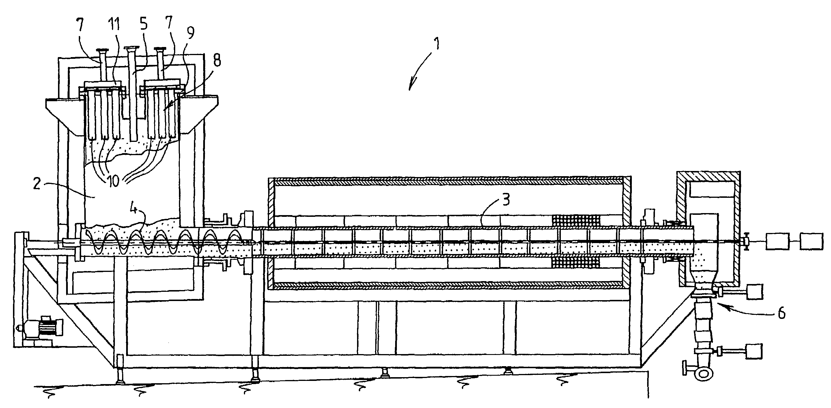
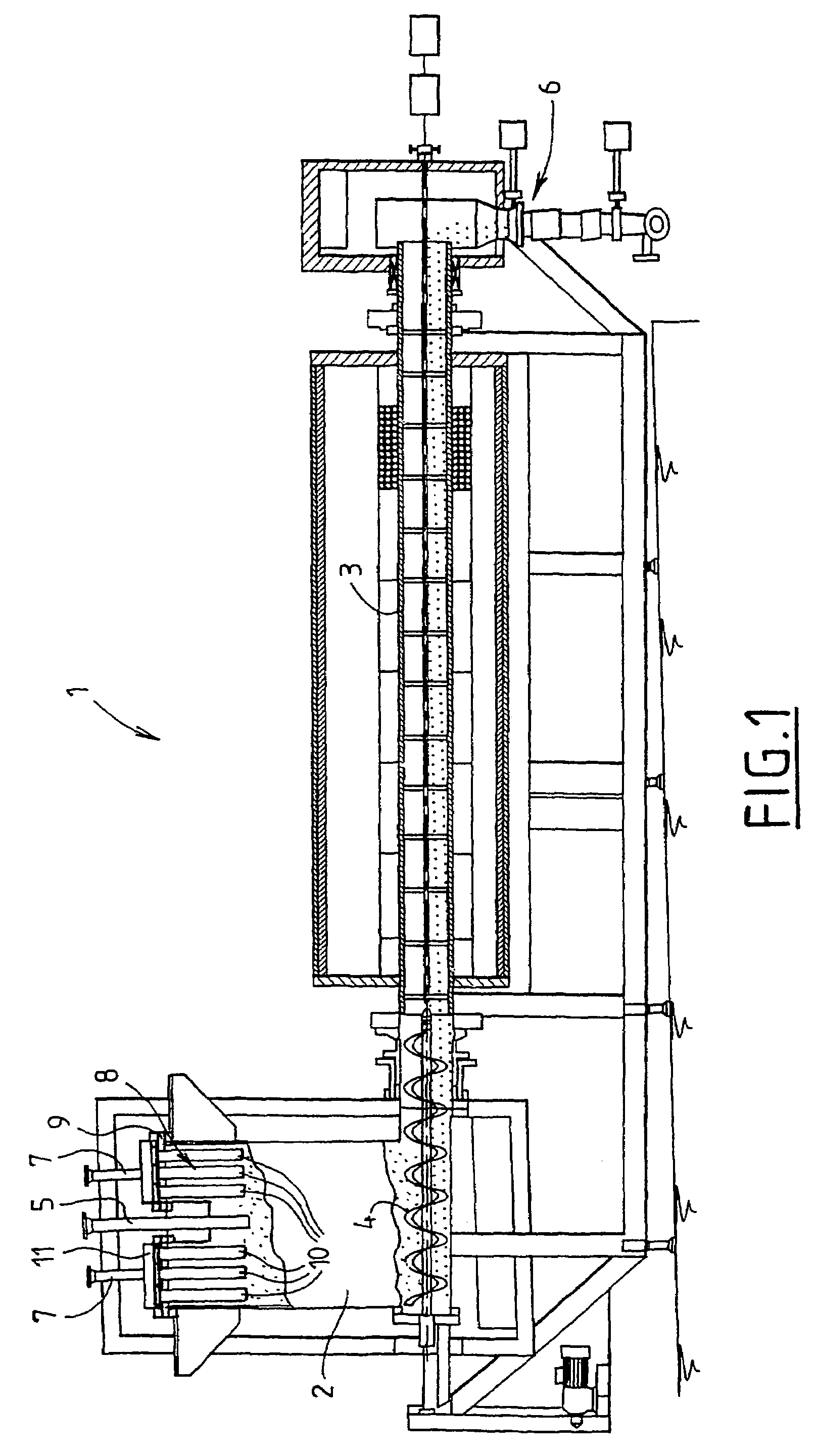
[0033]FIG. 1 illustrates a uranium oxide manufacturing plant generally denoted by the reference 1 and comprising a reactor 2 for converting uranium hexafluoride into uranium oxyfluoride and a rotary furnace 3 for converting uranium oxyfluoride into uranium oxide.

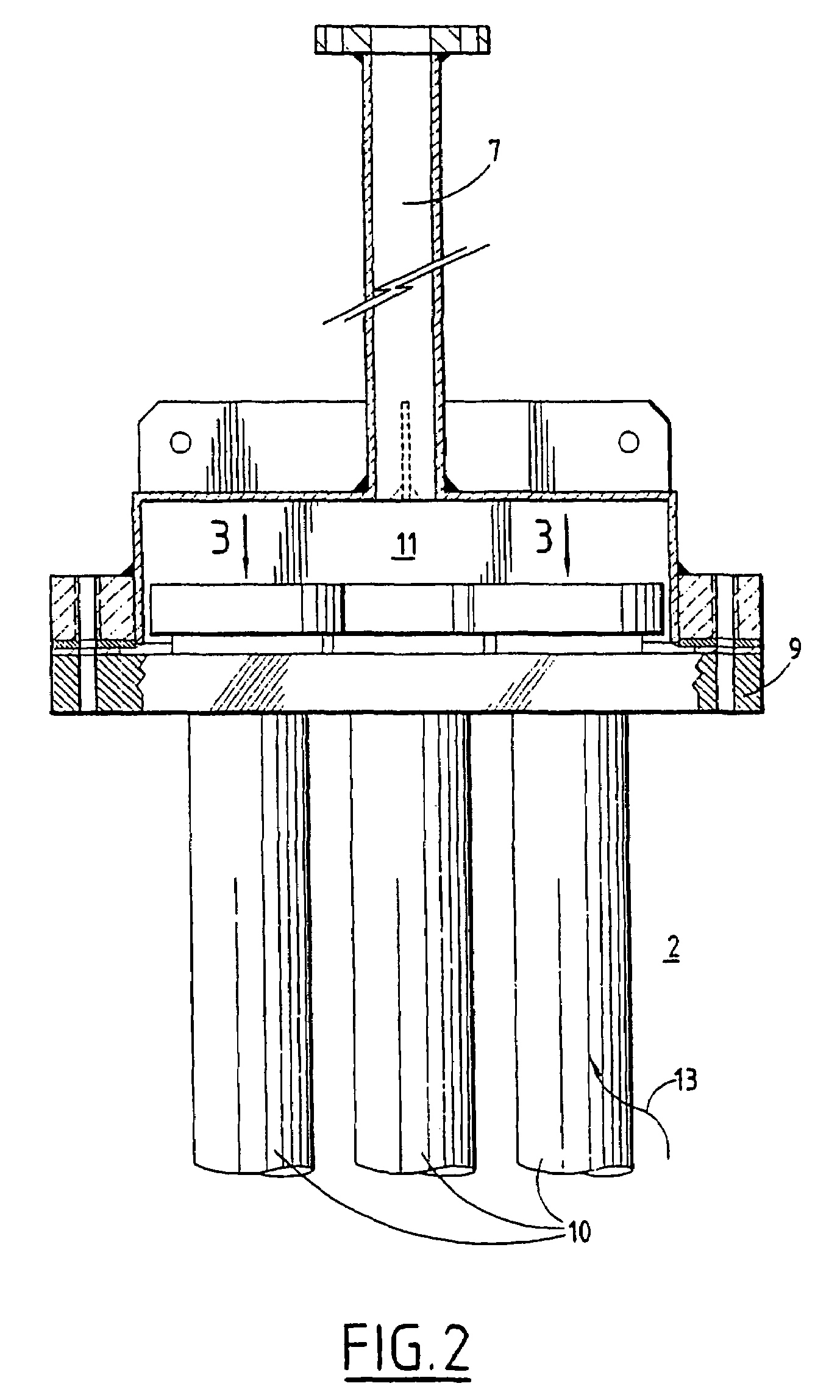
[0034]The reactor 2 has an enclosure generally placed in a vertical arrangement, in which emerges a pipe 5 for injecting reagent gases UF6 and H2O and a dilution gas which may be an inert gas such as nitrogen, inside the enclosure of the reactor 2.

[0035]Hydrolysis of uranium hexafluoride UF6 by steam occurs in the reactor 2, so as to form powdered uranium oxyfluoride which falls to the bottom of the reactor 2 and which is taken up by a conveying screw 4 which conveys the uranium oxyfluoride in powdered solid form formed in the reactor 2 to the input of the rotary furnace 3 in which the uranium oxyfluoride is converted into uranium oxide (mainly UO2).

[0036]The hydrolysis reaction of uranium hexafluoride produces gaseous hydro...


PUM

PropertyMeasurementUnit
velocityaaaaaaaaaa
velocityaaaaaaaaaa
initial pressureaaaaaaaaaa

Abstract

A method of declogging at least one filter of a plant for manufacturing uranium oxide from uranium hexafluoride, including separating, from the wall of the filter, uranium oxyfluoride particles deposited, by a stream of inert gas such as nitrogen, injected into the filter, in a counter-currentwise direction to the flow of hydrofluoric acid.

Description

FIELD OF INVENTION[0001]The invention relates to a method and a device for declogging a filter of a plant for manufacturing uranium oxide from uranium hexafluoride.BACKGROUND INFORMATION[0002]Uranium oxide manufacturing plants implementing a dry method of manufacturing uranium oxide from gaseous uranium hexafluoride UF6 coming from a plant for enriching uranium used as a nuclear fuel with radioactive isotopes.[0003]Such plants implementing the method of manufacturing uranium oxide from uranium hexafluoride, called dry conversion method, comprise, in an industrial embodiment which is currently the most satisfactory and most widespread embodiment, a reactor having an overall vertical arrangement into which uranium hexafluoride UF6, steam and dilution nitrogen are introduced, at a temperature of 200° C. to 300° C., and uranium hexafluoride UF6 is converted into uranium oxyfluoride UO2F2 according to the hydrolysis reaction:UF6+2H2O→UO2F2+4HF.[0004]The conversion of uranium hexafluoride...

Claims


Application Information

Patent Timeline
Patent Type & Authority Patents(United States)
IPC IPC(8): B01D41/00B01D46/04B01J19/00C01G43/01C01G43/06B01D46/00B01D46/24B01D46/42C01G43/025
CPCB01D46/0005B01D46/0058B01D46/0068B01D46/0093B01D46/0094B01D46/0069C01B7/191C01B7/195C01G43/01C01G43/06C01G43/063B01D46/2411B01D46/90B01D46/715B01D46/71B01D46/42
Inventor FEUGIER, ANDRE
Owner AREVA NP SAS
Why Eureka
Try Eureka