Power supply for a load control device

a technology of load control device and power supply, which is applied in the direction of electric variable regulation, process and machine control, instruments, etc., can solve the problems of inability to control the fan motor and lighting load from more than one location, and inability to independently control the lighting load and the fan motor

Active Publication Date: 2008-09-09
LUTRON TECH CO LLC
View PDF29 Cites 66 Cited by
  • Summary
  • Abstract
  • Description
  • Claims
  • Application Information

AI Technical Summary

Benefits of technology

[0012]The present invention further provides a power supply adapted to be disposed in series electrical connection between an electrical load and an AC voltage source and operable to generate a DC voltage. The power supply comprises a controllably conductive device having a control input, a triggering circuit, and a charging circuit. The controllably conductive device is adapted to carry a load current from the AC voltage source to the electrical load when the controllably conductive device is conductive. The triggering circuit is coupled to the control input of the controllably conductive device for causing the controllably conductive device to become conductive. The charging circuit is operable to charge an energy storage capacitor when the controllably conductive device is non-conductive such that the DC voltage is produced across the energy storage capacitor. The charging circuit imposes a low voltage drop relative to the peak value of an AC voltage of the AC voltage source such that substantially all of the AC voltage is available to the load during the time when the controllably conductive device is non-conductive. The charging circuit is operable to stop charging the energy storage capacitor when the controllably conductive device is conductive. The triggering circuit is operable to cause the controllably conductive device to become conductive in response to the DC voltage so as to cause the energy storage capacitor from charging.
[0013]According to another aspect of the present invention, a remote control device for an electrical load is adapted to be coupled in series electrical connection between the electrical load and an AC voltage source. The remote control device comprises a communication circuit, a controller, and a power supply. The communication circuit is operable to transmit control information for controlling the electrical load. The controller is coupled to the communication circuit for providing the control information to the communication circuit. The power supply is adapted to be coupled in series electrical connection between the electrical load and the AC voltage source and is operable to generate a DC voltage to power the communication circuit and the controller. The power supply comprises a charging circuit for charging an energy storage device. The charging circuit imposes a low voltage drop relative to the peak value of an AC voltage of the AC voltage source such that substantially all of the AC voltage is available to the load during the time when the energy storage device is charging.

Problems solved by technology

If these two connections are not provided between the wallbox and the enclosure containing the lamp and the fan motor, independent control of the lighting load and the fan motor will not be possible.
Control of the fan motor and lighting load from more than one location is not possible in this system.

Method used


Image

  • Power supply for a load control device
  • Power supply for a load control device
  • Power supply for a load control device

Examples


Embodiment Construction

[0024]The foregoing summary, as well as the following detailed description of the preferred embodiments, is better understood when read in conjunction with the appended drawings. For the purposes of illustrating the invention, there is shown in the drawings an embodiment that is presently preferred, in which like numerals represent similar parts throughout the several views of the drawings, it being understood, however, that the invention is not limited to the specific methods and instrumentalities disclosed.

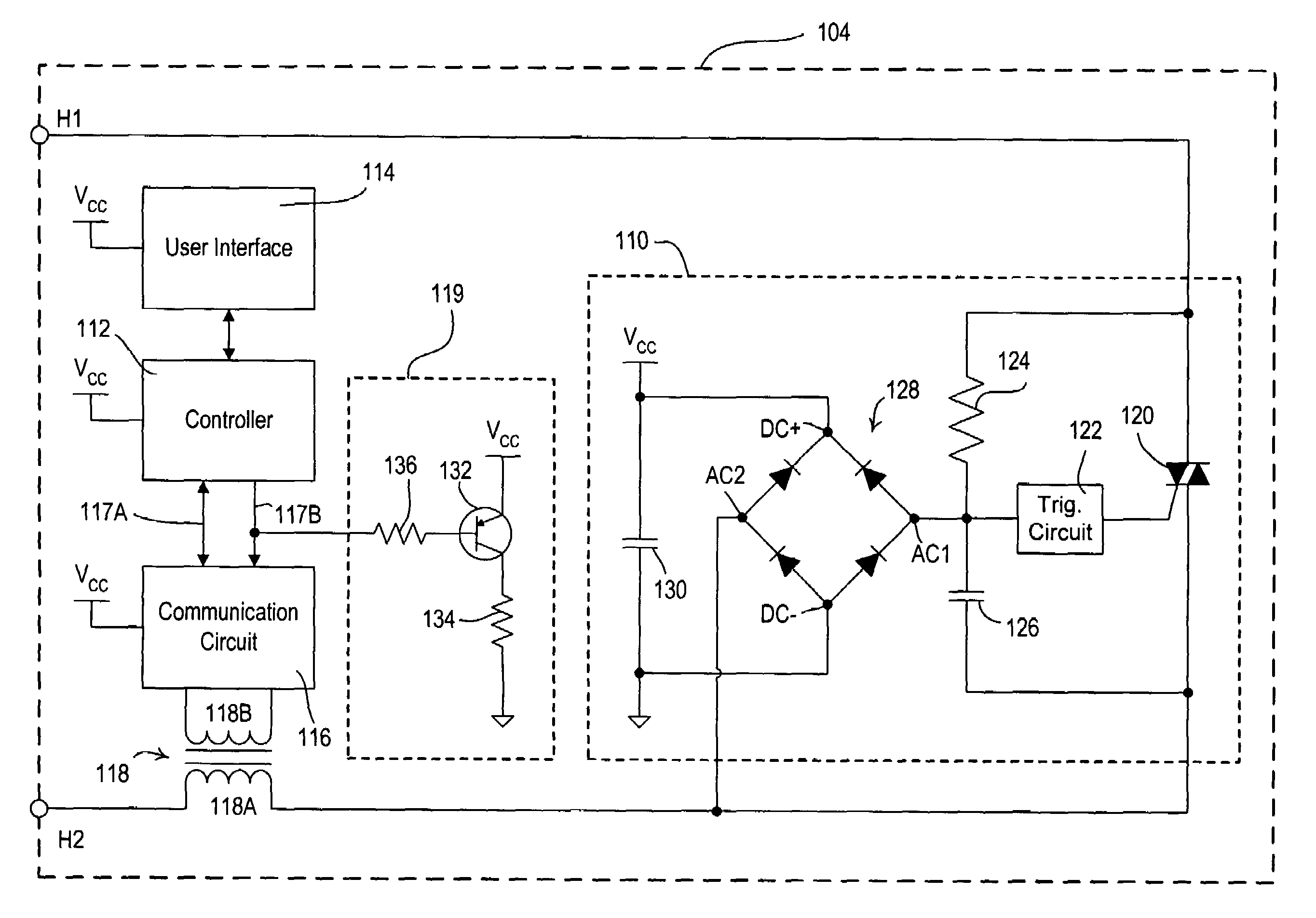
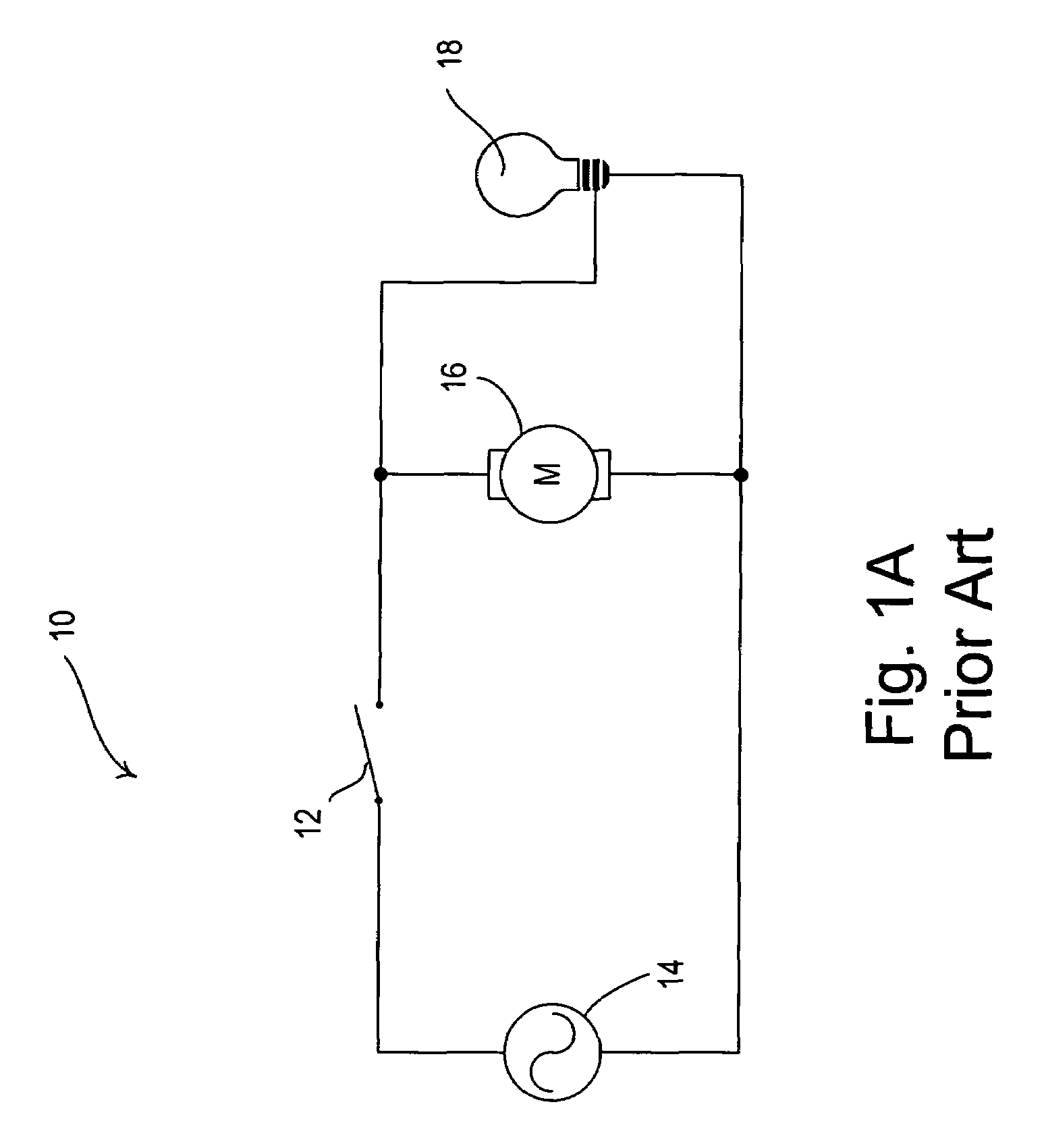
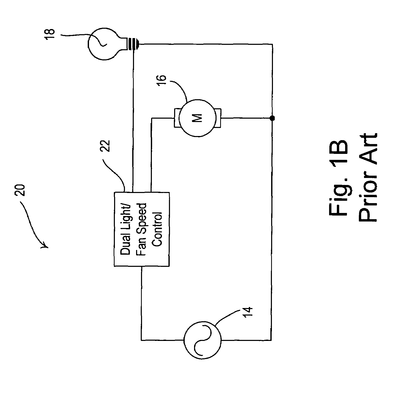
[0025]As is well known, a lamp and a fan motor are typically packaged in the same housing. It is desirable to be able to control the lamp and fan motor independently from the same remote location, for example, a wallstation. However, the two circuits to control the lamp and the fan motor are typically different. The lamp may be controlled by a series switch, typically a phase-angle dimmer. The fan motor may be controlled by a shunt switch in parallel with the fan motor, which is...


PUM


Abstract

A power supply for a load control device is disposed in series with an AC voltage source and a load and generates a substantially DC voltage for powering a controller of the load control device. The power supply is operable to provide substantially all voltage provided by the AC voltage source to the load and includes a controllably conductive device, a triggering device, and a charging circuit. The charging circuit is operable to charge an energy storage device and to conduct current to the load when the controllably conductive device is non-conductive. The controllably conductive device begins conducting the full load current when the energy storage device has charged to a predetermined amount of energy. Before the controllably conductive device begins to conduct, only a minimal voltage, which is substantially the same as the break-over voltage of the triggering circuit, develops across the power supply to allow the energy storage device to charge.

Description

RELATED APPLICATIONS[0001]This application claims priority from commonly-assigned U.S. Provisional Application Ser. No. 60 / 687,691, filed Jun. 6, 2005, and from commonly-assigned U.S. Provisional Application Ser. No. 60 / 738,083, filed Nov. 18, 2005, both having the same title as the present application. The entire disclosures of both provisional applications are hereby incorporated by reference.BACKGROUND OF THE INVENTION[0002]1. Field of the Invention[0003]The present invention relates to an apparatus for independently controlling a motor, for example, a fan motor, together with a lighting source contained within the same enclosure as the fan motor or coupled to the fan motor. More specifically, the invention relates to a power supply for a remote control device for providing individual control of the lighting source and the fan motor.[0004]2. Description of the Related Art[0005]It is often desirable to include a lamp in the same enclosure as a fan motor. Since the lamp and the fan...

Claims


Application Information

Patent Timeline
Patent Type & Authority Patents(United States)
IPC IPC(8): G05F1/455H02J3/12
CPCH02M5/257H05B39/08H02M5/2573H02M2001/0006H02M1/0006
Inventor DOBBINS, AARONWEIGHTMAN, RUSSELLPERREAULT, DAVID JSTEINER, JAMES PWU, CHEN MING
Owner LUTRON TECH CO LLC
Why Eureka
Try Eureka