
Motion sensors integrated within an electro-hydraulic control unit

a technology of electro-hydraulic control unit and motion sensor, which is applied in the association of printed circuit non-printed electric components, process and machine control, instruments, etc., can solve problems such as troublesome shoot components, and achieve the effects of simplifying the servicing of the control system, eliminating wiring, and facilitating the connection to the hydraulic brake lin

Active Publication Date: 2008-09-09
KELSEY HAYES CO
View PDF19 Cites 22 Cited by
  • Summary
  • Abstract
  • Description
  • Claims
  • Application Information

AI Technical Summary

Benefits of technology

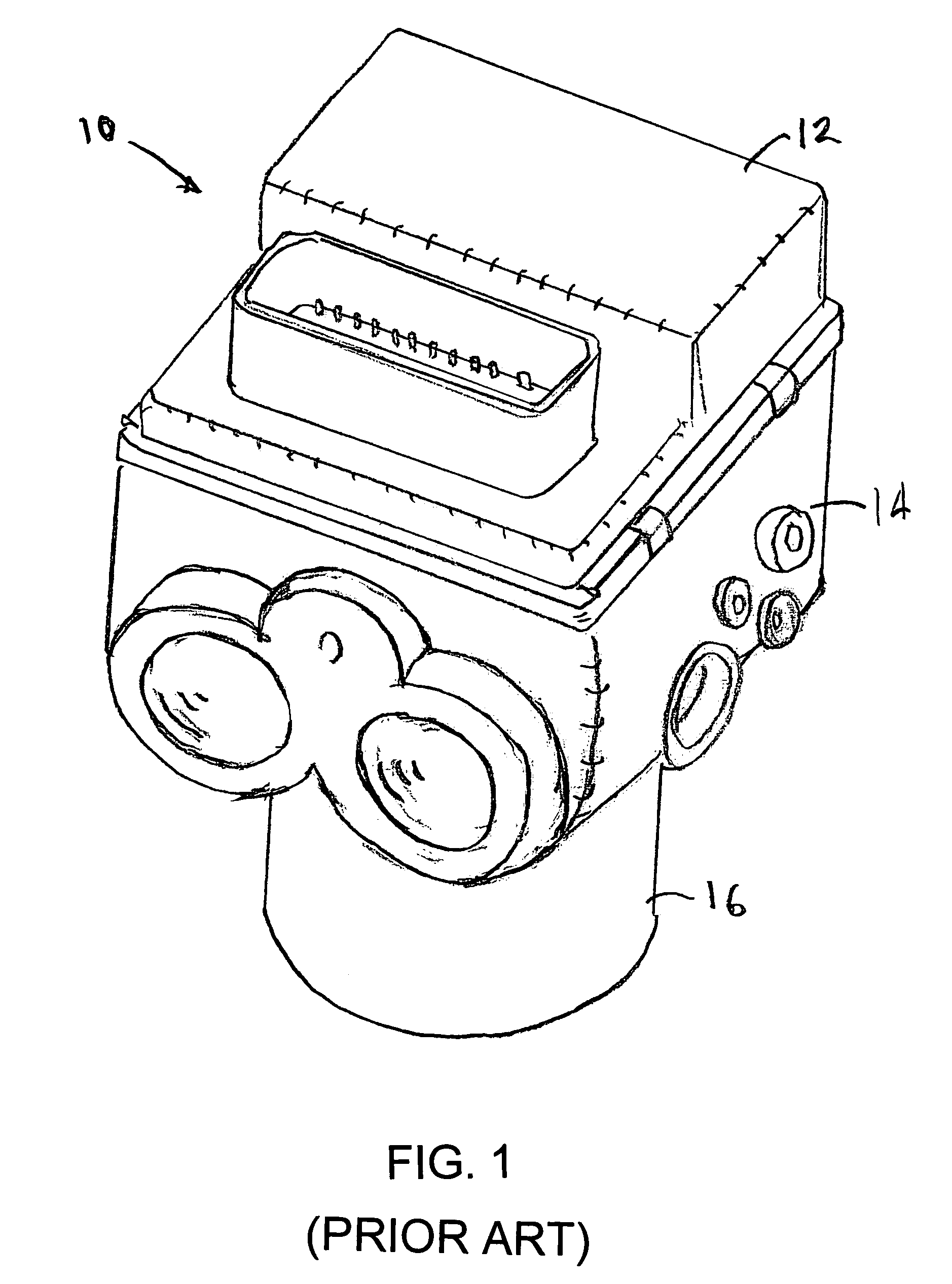
[0010]As described above, it is known to include acceleration sensors and angular rate sensors in brake control systems. However, the sensors are typically located separately from the electronic control unit. Usually, the ECU is mounted upon the valve body and the valve body is typically located in either the vehicle engine compartment on upon the vehicle chassis to facilitate connection to the hydraulic brake lines. The motion sensors, on the other hand, are typically located in the passenger compartment, at or near the vehicle's center of gravity. Accordingly, it is necessary to route wiring from the engine compartment to the passenger compartment to connect the motion sensors to the microprocessor in the ECU. Additionally, it is necessary to trouble shoot components in two separate locations when servicing is needed. Therefore, it would be desirable to mount the motion sensors within the ECU and thereby eliminate the wiring between the engine and passenger compartments. Alternately, it would be desirable to mount the motion sensors within an ECU that is located in the passenger compartment to simplify servicing of the control system.

Problems solved by technology

Additionally, it is necessary to trouble shoot components in two separate locations when servicing is needed.

Method used


Image

  • Motion sensors integrated within an electro-hydraulic control unit
  • Motion sensors integrated within an electro-hydraulic control unit
  • Motion sensors integrated within an electro-hydraulic control unit

Examples


Embodiment Construction

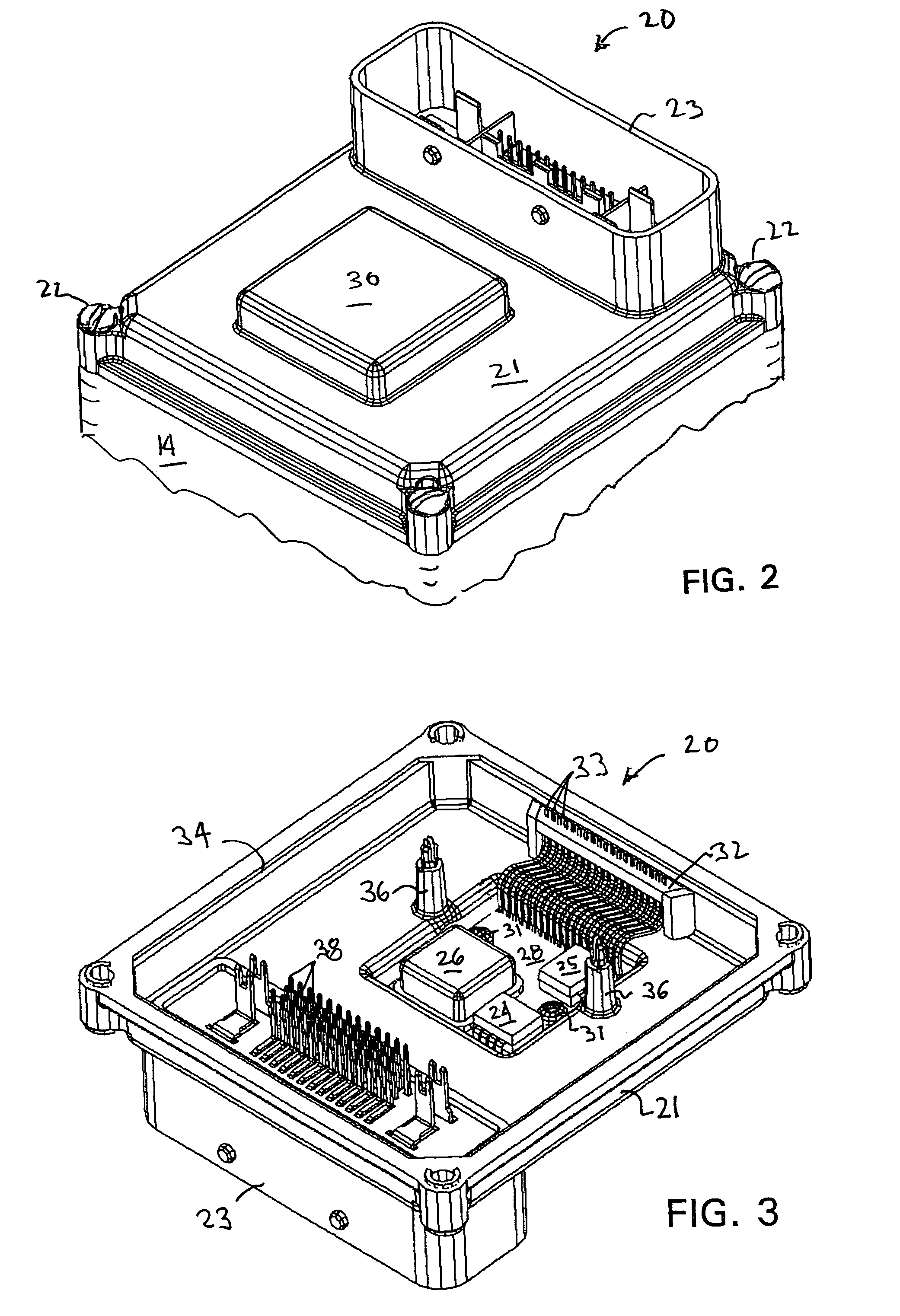
[0034]Referring again to the drawings, there is illustrated in FIG. 2, an ECU 20 in accordance with the invention. The ECU 20 includes a housing 21 formed from plastic or metal by a conventional method, such as injection molding or die casting. The ECU 20 is shown in FIG. 2 as being removeably attached to a hydraulic valve body 14 by a plurality of fasteners 22. The housing 21 includes an integrally formed electrical connector 23 that provides electrical connections between the ECU 20 and wiring to the vehicle power supply, wheel speed sensors and other electrical components of the vehicle.

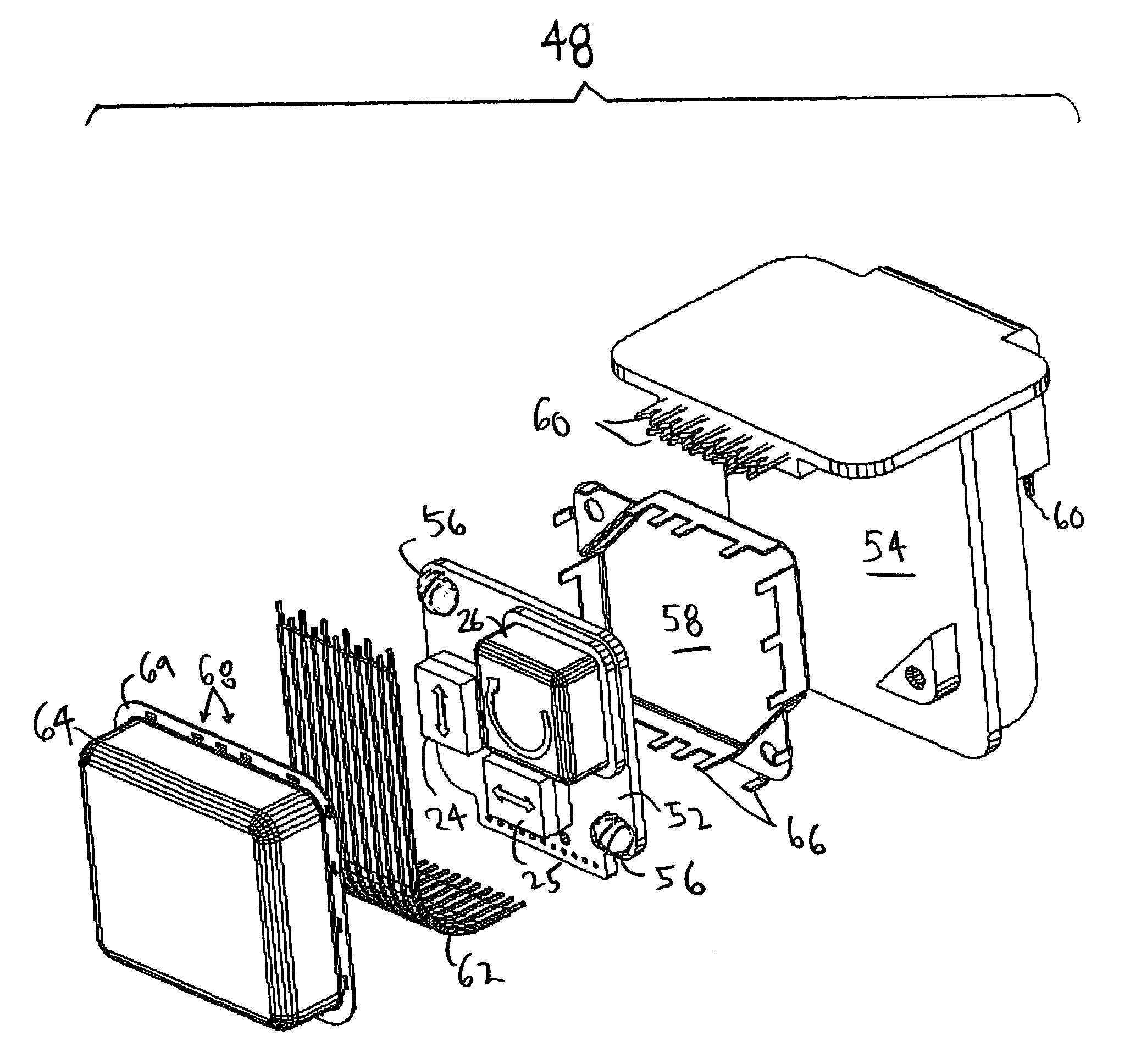
[0035]As best seen in FIG. 3, which shows the inside of the ECU housing 21 as viewed from below the housing, the ECU 20 includes two acceleration sensors, 24 and 25 and one angular rate, or gyroscopic, sensor 26 mounted upon a circuit substrate 28. The circuit substrate 28 is disposed within a recess 30 formed in the upper surface of the ECU housing 21. The circuit substrate 28 is retained in the ...


PUM


Abstract

An electronic control unit for a vehicle system that includes at least one acceleration sensor and at least one angular rate sensor for generating data concerning motion of the vehicle relative to vehicle reference axes.

Description

CROSS REFERENCE TO RELATED APPLICATIONS[0001]This application is a continuation-in-part of co-pending International patent application No. PCT / US02 / 23134 filed on Jul. 19, 2002, and claims the benefit of U.S. Provisional patent application Nos. 60 / 306,622 and 60 / 352,605 filed on Jul. 19, 2001, and Jan. 29, 2002, respectively. International patent application No. PCT / US02 / 23134 was published as WO 03 / 008244 on Jan. 30, 2003, in English under PCT Article 21(2)BACKGROUND OF THE INVENTION[0002]This invention relates in general to Electronic Control Units for controlling a vehicle brake system and in particular to integration of vehicle motion sensors into an Electronic Control Unit.[0003]Many vehicles being currently produced by automotive manufacturers include automatic brake control systems that are integrated with their hydraulic brake systems. Such systems include Anti-lock Brake Systems (ABS) that prevent wheel lock-up during braking cycles, Vehicle Stability Control (VSC) systems ...

Claims


Application Information

Patent Timeline
Patent Type & Authority Patents(United States)
IPC IPC(8): H05K1/18G01P15/18B60T8/171B60G17/019B60G17/0195B60G17/04B60G17/056B60R16/02B60R16/023B60T8/17B60T8/36
CPCB60G17/019B60G17/0195B60G17/0408B60G17/056B60T8/3685B60R16/0239B60T8/3675B60T8/368B60G2206/0116B60G2400/051B60G2400/1042B60G2401/28B60G2500/203B60G2400/102
Inventor BABALA, MICHAEL L.BOLITHO, MARCTHOMAS, GORDONLEWIN, DOUGGEGALSKI, HELMUTBUSTGENS, BURKARDKAPPEN, NICODEMUSBARRON, THOMAS
Owner KELSEY HAYES CO
Learn More