
Device for compensating the weight of a suspended load

a technology for compensating devices and suspended loads, which is applied in the direction of hoisting equipment, manufacturing tools, work benches, etc., can solve the problems of limited transfer of necessary torque, high cost, and inability to implement in practice, and achieves strong torque, reduced cost, and strong torque.

Active Publication Date: 2008-09-16
CARL STAHL KROMER
View PDF13 Cites 7 Cited by
  • Summary
  • Abstract
  • Description
  • Claims
  • Application Information

AI Technical Summary

Benefits of technology

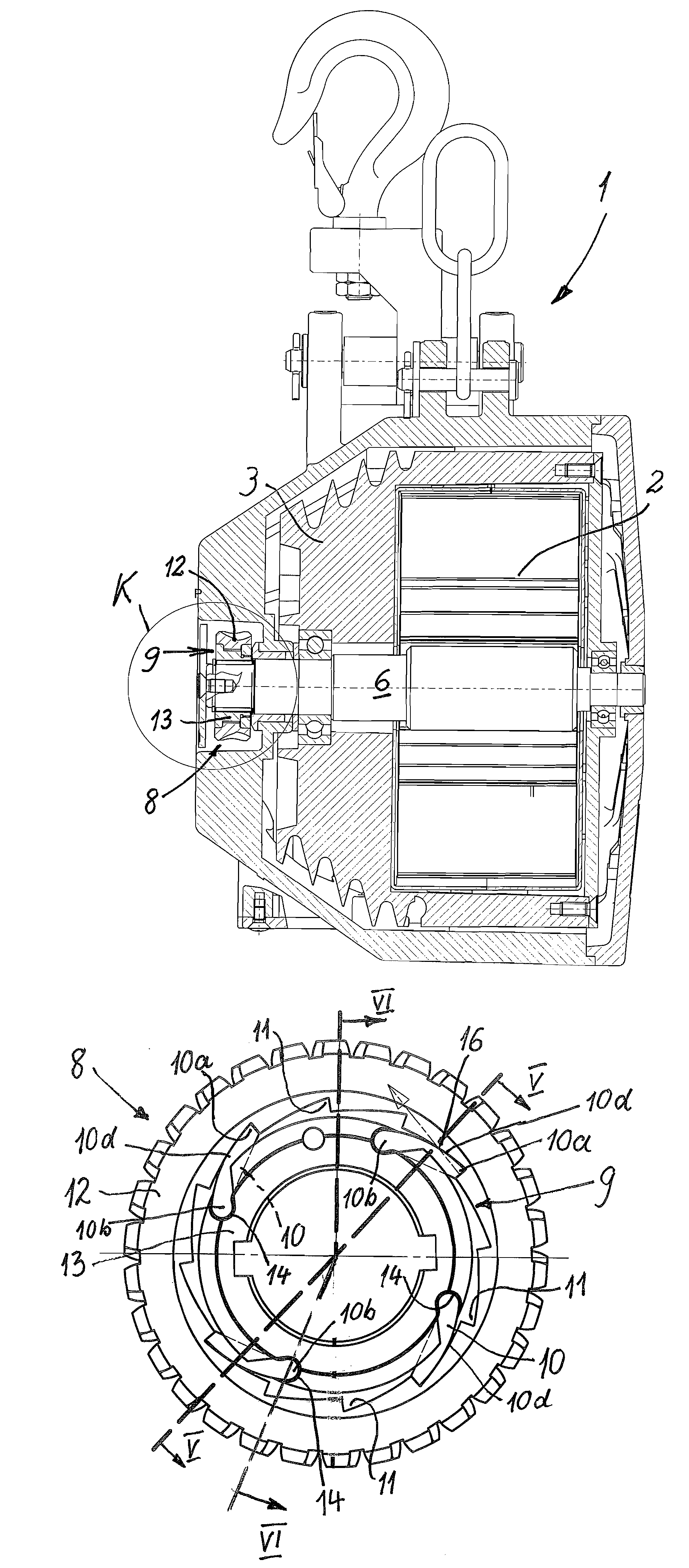
[0005]In this way, a clamping brake is replaced by a catching latch arrangement transferring considerably stronger torque. The seemingly higher expense of three or preferably four or more latches in reference to a common catching latch arrangement having one or two latches allows a transfer of a relatively strong torque in the blocking direction, with the forces developing here being distributed over several latches, so that based on the small space requirement, relatively small latches are still able to match these forces. Simultaneously, a roller bearing frequently provided in such freewheels is avoided, which also would have required a lot of space. Rather, the interior body of the catching latch arrangement fulfills a dual function, in which, on the one hand, the latches can be pivoted radially outwards and, on the other hand, are supported at the circular drive ring of the drive wheel.
[0019]Primarily combinations of individual or several of the above-described features and measures result in a spring tensioner for compensating the weight of a suspended load, in which a strong torque can be transferred on a very small space at a drive wheel and its circular drive wheel, without risking that a latch of the catching latch arrangement provided is insufficient for the load developing here. Simultaneously a relatively cheap production results in that a roller bearing in the area of the drive wheel is avoided and a catching latch arrangement is used which in spite of the use of at least three latches, can be produced cheaper than a clamping brake and can transfer the already mentioned stronger torque.

Problems solved by technology

Such a device for compensating the weight of a suspended load in the form of spring tensioner is known from DE 35 12 112 A1; however, it has not been implemented in practice.
This primarily is because the free wheel described in this preliminary publication is disclosed for one rotational direction as a friction clutch and for the other rotational direction as a clamping brake, which represents an expensive arrangement.
Furthermore, the transfer of the necessary torque is limited when using, on the one hand, a friction clutch and, on the other hand, a clamping brake, in particular due to the only very limited space available inside the drive wheel of a spring tensioner, and furthermore the production of a clamping brake is expensive.
Particularly, the clamping brake disclosed in the preliminary publication as a preferred means to prevent the disconnection or disengagement of the interior spring end from the shaft is not well suited to transferring strong torques.

Method used


Image

  • Device for compensating the weight of a suspended load
  • Device for compensating the weight of a suspended load
  • Device for compensating the weight of a suspended load

Examples


Embodiment Construction

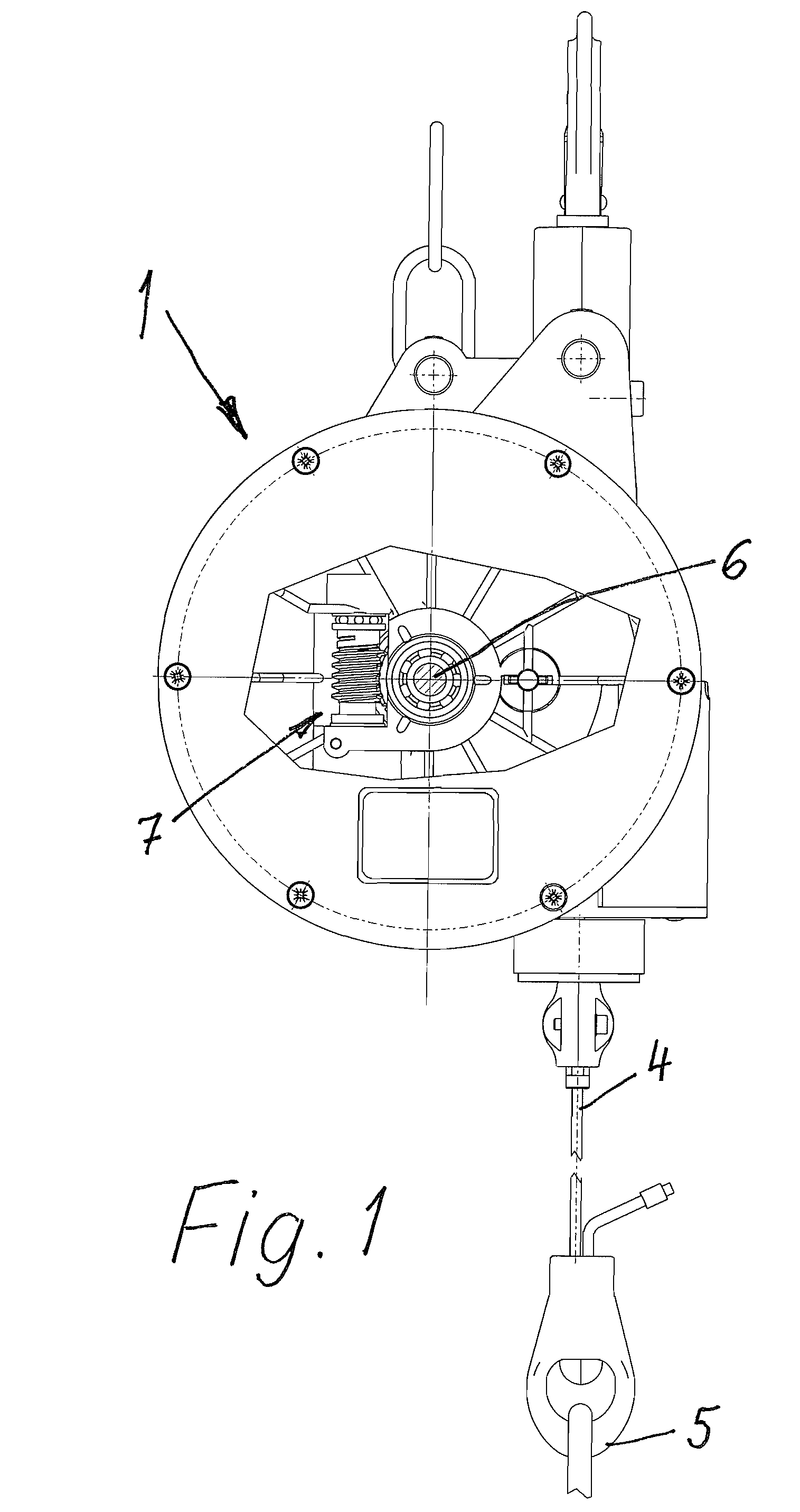
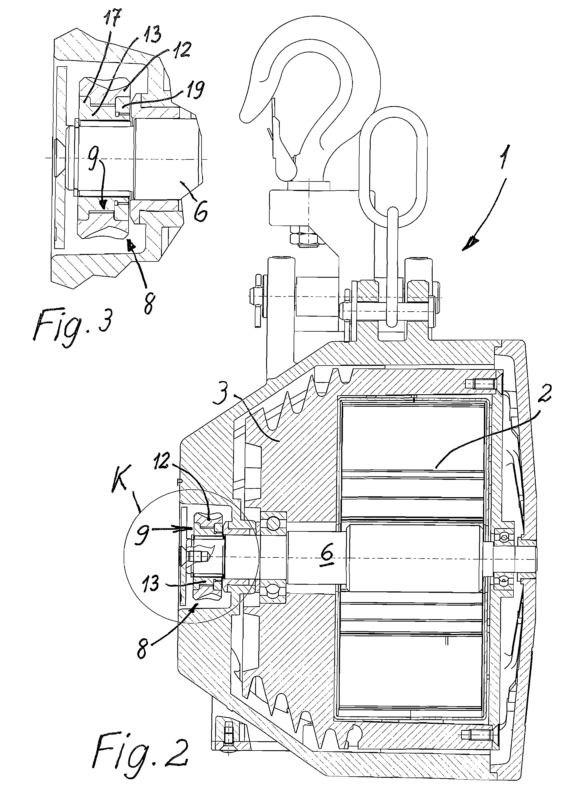
[0027]The device, in its entirety marked 1, serves to compensate the weight of a suspended load not shown in greater detail, for example a tool or welding tongs to be manually operated and is embodied as a spring tensioner referred to as “spring tensioner 1” in the following.

[0028]This device 1 and / or its spring tensioner 1 is provided with a tackle 4 against the force of a spring 2, in the exemplary embodiment a helical coiled leaf spring that can be reeled off a conical barrel 3, essentially embodied as a supporting wire for the suspended load and provided therefore with an engagement device 5.

[0029]The barrel 3 is supported rotational on a shaft 6 normally horizontal in the operational state, to which the spring 2 is directly engaged with its interior end or via a sheath connected to the shaft 6, as overall known from DE 3 512 112 A1, which is incorporated herein by reference as if fully set forth.

[0030]The exterior end of the spring 2 engages in a manner also known per se at the...


PUM


Abstract

A device (1) that compensates the weight of a suspended load, for example a tool or welding tongs, is provided as a spring tensioner with at least one barrel (4) or supporting wire that can be reeled off a barrel (3) against the force of a spring (2). The barrel (3) is supported on a shaft (6), to which the spring (2) engages directly with its interior end or via a sheath connected to the shaft (6), while the opposite exterior end of the spring (2) is mounted to the barrel (3) at the inside. A shaft drive (7) can be activated to change the pull force at the spring (2) via the shaft (6). The spring (2) is connected to the shaft drive (7) or to a drive wheel (8) allocated thereto via a freewheel. The freewheel is embodied with a catching latch arrangement (9) which, in the blocking direction has at least three or four latches (10) that simultaneously engage the recesses or catching recesses (11) which receive them, said latches being arranged at the inside at a circular drive wheel (12) allocated to a drive wheel (8). An interior body (13) of the catching latch arrangement located inside the circular drive wheel (12) supports the latches (10) and is simultaneously a part of a slide bearing for the circular drive wheel (12) for rotation in the freewheel direction. In this way, in a small space strong forces can be transferred.

Description

BACKGROUND[0001]The invention relates to a device for compensating a suspended load, in particular a tool or welding tongs to be operated manually, in the form of a counterweight or a spring tensioner with at least one spring, in particular a coil spring or a coiled leaf spring, operating against the force, a suspension wire that can be reeled off a barrel, with the barrel being supported rotationally on a shaft, directly engaged by the spring with its internal end or via a sheath connected to the shaft, while the external end of the spring engages the barrel, with the shaft drive acting on the spring to change the support via the shaft, and the spring being connected to the shaft drive and a drive wheel arranged on the shaft and allocated to the shaft drive via a freewheel, which responds in the sense of a free wheel with its internal end when the spring is relaxed prior to disconnection or disengagement.[0002]Such a device for compensating the weight of a suspended load in the for...

Claims


Application Information

Patent Timeline
Patent Type & Authority Patents(United States)
IPC IPC(8): B66D1/14
CPCB25H1/0028B65H75/483B65H75/4428
Inventor ACHTARI, MOHAMMAD S.STEINLE, THOMAS
Owner CARL STAHL KROMER
Learn More