
Engine PCV system with venturi nozzle for flow regulation

a technology of flow regulation and nozzle, which is applied in the direction of combustion engines, charge feed systems, non-fuel substance addition to fuel, etc., can solve the problems of generating noise at certain points of instability, reducing the efficiency of pcv systems, so as to achieve low cost and simple design

Active Publication Date: 2008-10-07
GM GLOBAL TECH OPERATIONS LLC
View PDF8 Cites 24 Cited by
  • Summary
  • Abstract
  • Description
  • Claims
  • Application Information

AI Technical Summary

Benefits of technology

The present invention provides a PCV system for an internal combustion engine that uses a venturi nozzle to regulate flow in place of a spring-loaded PCV valve or a simple orifice. The venturi nozzle is a low-cost and simple design that can maintain a constant flow rate over most of the range of pressure differentials present in the PCV system. The PCV system includes a cylinder air intake system and a filtered air inlet to a crankcase for admitting air to mix with crankcase vapors and other crankcase vapors. The engine also includes a throttle and a venturi nozzle to control the flow of crankcase vapors into the inlet air passing to the engine cylinders. The venturi nozzle is designed to reach sonic flow velocity during most of the engine operating range, thereby controlling PCV vapor flow at a constant value. The technical effects of the invention include improved engine performance, reduced emissions, and improved fuel efficiency.

Problems solved by technology

While a spring-loaded PCV valve provides a generally constant flow rate above a certain pressure differential, it has a relatively higher cost than a simple orifice and can potentially generate noise at certain points of instability.
On the other hand, while a simple orifice design is relatively less complex and less expensive, it provides less than ideal flow regulation for some of the range of pressure differentials present in the PCV system during engine operation.

Method used


Image

  • Engine PCV system with venturi nozzle for flow regulation
  • Engine PCV system with venturi nozzle for flow regulation
  • Engine PCV system with venturi nozzle for flow regulation

Examples


Embodiment Construction

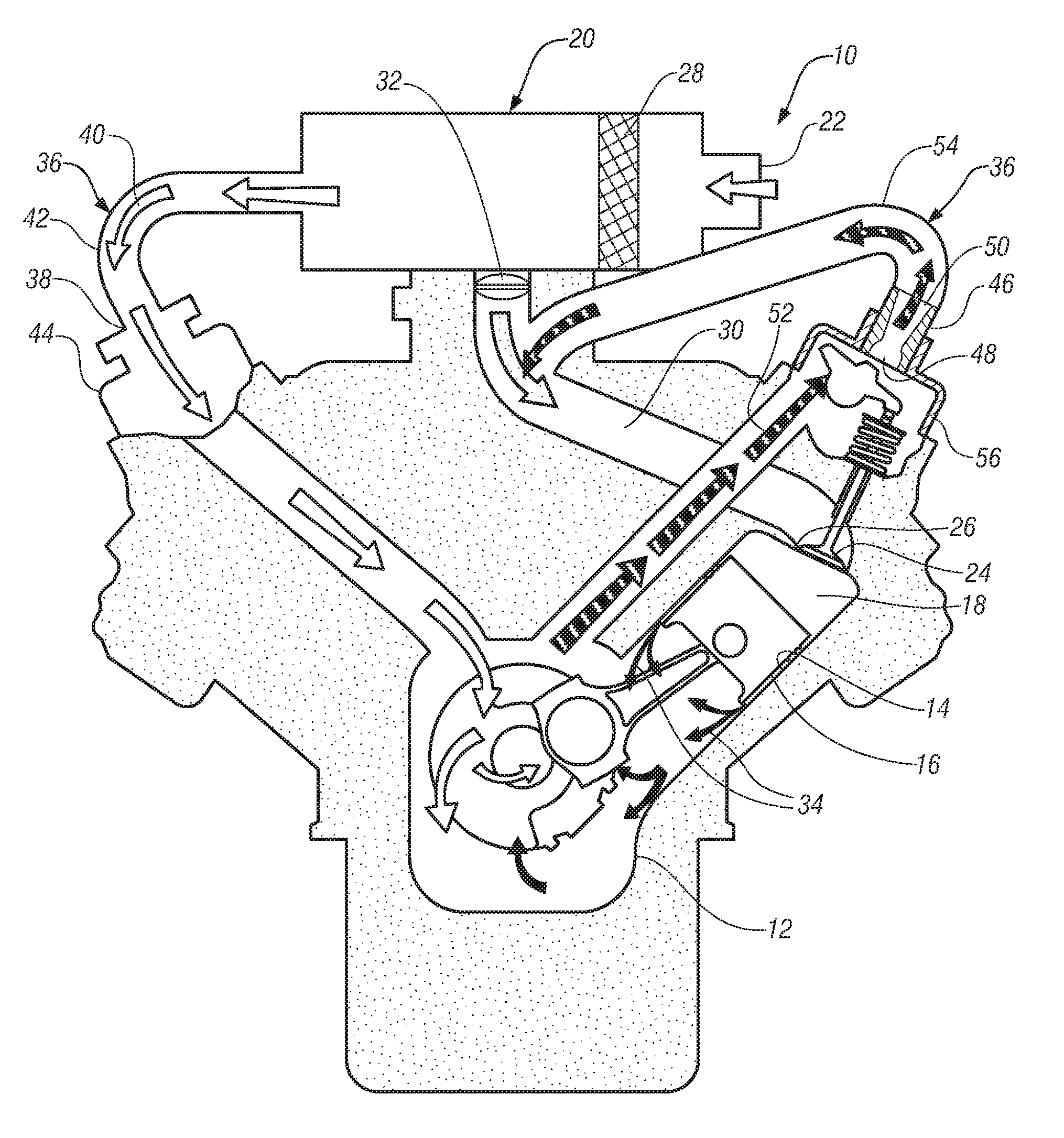
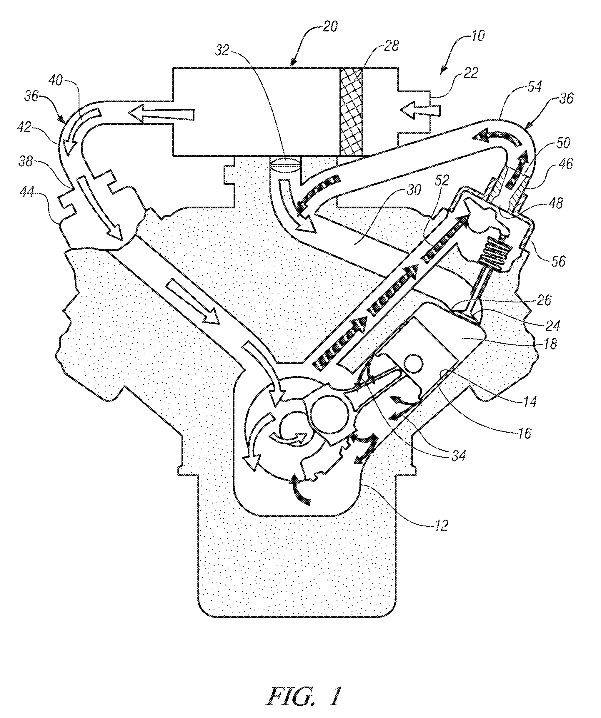
[0011]Referring now to the drawings in detail, numeral 10 generally indicates an internal combustion engine in accordance with the present invention. The internal combustion engine 10 generally includes a crankcase 12 and at least one cylinder 14. A piston 16 is reciprocable in each cylinder 14 and defines a variable volume combustion chamber 18 therein. A filtered cylinder air intake system 20 is in fluid communication with each combustion chamber 18. The cylinder air intake system 20 generally extends from the fresh air inlet 22 to the cylinder intake valves 24 located in the cylinder intake ports 26. The cylinder air intake system 20 may include one or more of an air filter 28, a supercharger assembly (not shown), and an air intake manifold 30. A throttle 32 is also disposed in the cylinder air intake system 20 for controlling cylinder intake airflow to the associated cylinders 14. The cylinder air intake system 20 may alternatively be referred to as an air induction system.

[0012...


PUM


Abstract

A positive crankcase ventilation system for an internal combustion engine is disclosed. The system includes an engine having a cylinder air intake system connected to associated cylinders and a filtered air inlet to a crankcase for admitting air to mix with crankcase vapors. A throttle is disposed in the cylinder air intake system for controlling airflow to the associated cylinders. The system further includes a venturi nozzle having an inlet and an outlet. The venturi nozzle inlet is connected to the crankcase for receiving the mixture of filtered air and crankcase vapors. The venturi nozzle outlet is connected to the cylinder air intake system at a location subject to variable intake vacuum pressure between the throttle and the cylinders to allow the mixture of filtered air and crankcase vapors to be drawn into the inlet air passing to the cylinders downstream of the throttle.

Description

TECHNICAL FIELD[0001]This invention relates to positive crankcase ventilation (PCV) systems, and more particularly to flow regulation in PCV systems.BACKGROUND OF THE INVENTION[0002]It is known in the art relating to internal combustion engines to use a positive crankcase ventilation (PCV) system to remove crankcase vapors (including unburned fuel and combustion products that leak past the piston rings, oil vapors, and other vapors present in the crankcase) from the crankcase. PCV systems recirculate crankcase vapors in lieu of exhausting the vapors to the atmosphere, thereby reducing engine emissions while also advantageously improving engine efficiency and increasing engine life. Generally, PCV systems utilize engine vacuum to draw fresh air from an engine air intake system through the crankcase. The level of engine vacuum varies with engine operating conditions (i.e., idle, acceleration, constant speed, deceleration). During periods of engine idle or deceleration, engine vacuum i...

Claims


Application Information

Patent Timeline
Patent Type & Authority Patents(United States)
IPC IPC(8): F02M25/06
CPCF01M13/022F01M13/023
Inventor KAVANAGH, SCOTT A.STILES, DAVID K.SPIX, THOMAS A.
Owner GM GLOBAL TECH OPERATIONS LLC
Learn More