Substrate heat treatment apparatus

a heat treatment apparatus and substrate technology, applied in the direction of charge manipulation, furnaces, muffle furnaces, etc., can solve the problems of unevenness, inability to make full use of the highly precise temperature uniformity, and the minute space between the bake plate and the substrate cannot be uniform over the entire surface of the substrate, so as to achieve the effect of increasing the uniformity

Active Publication Date: 2008-10-07
DAINIPPON SCREEN MTG CO LTD
View PDF9 Cites 351 Cited by
  • Summary
  • Abstract
  • Description
  • Claims
  • Application Information

AI Technical Summary

Benefits of technology

[0012]Where the exhaust bores open to the upper surface of the bake plate, suction may easily be applied to the substrate surface to draw the substrate toward the bake plate. This realizes an efficient sucking action.
[0016]When the substrate is placed in the apparatus, the support portion of the seal unit supports the periphery of the lower surface of the substrate at the height of the projections, and the regulator restricts sideways movement of the substrate, thereby preventing displacement of the substrate. Further, there is a possibility that the treating liquids and other substances from various processes have flowed round to and remain on the periphery of the lower surface of the substrate. When the substrate is sucked with such liquids and substances adhering to the support portion it may be difficult to separate the periphery of the substrate from the support portion upon cancellation of the suction. Thus, the contact portion smaller than the outside diameter of the substrate contacts and supports the lower surface of the substrate, and the groove maintains, out of contact, the periphery of the lower surface of the substrate possibly having the liquids and substances. Consequently, the substrate is readily separable from the seal unit even if the treating liquids and the like remain adhering to the periphery of the lower surface of the substrate.
[0018]When a gas were supplied through the exhaust bores having exhausted the gas from the minute space, in order to cancel the suction in the minute space to release the substrate, particles and the like could be blown upward toward the lower surface of the substrate to contaminate the substrate. Thus, the feed bores different from the exhaust bores are provided as above. When canceling the suction, the negative pressure in the minute space is positively canceled by first supplying the gas through the feed bores and thereafter the exhaust through the exhaust bores is stopped. This process effectively prevents the blowing-up of particles and the like, thereby treating the substrate in a highly clean condition. Further, by the influence of the treating liquids having flowed round to the lower surface of the substrate, the substrate may stick to the seal unit, making it difficult to separate the substrate even after the negative pressure is canceled. However, the gas is positively supplied to apply a pressure for raising the substrate, whereby the substrate is separated with ease.
[0020]The exhaust pressure detecting device detects an exhaust pressure. When the determining device determines an abnormality having occurred with the exhaust system based on the exhaust pressure, the reporting device reports the abnormality. Thus, it is possible to make known beforehand a situation where the heat treatment of the substrate becomes uneven because the minute space cannot be maintained at a sufficiently negative pressure due to the abnormality of the exhaust system. This prevents improper treatment being performed continuously.
[0024]With this construction, the seal unit closes the side of minute space between the lower surface of the substrate and the upper surface of the bake plate. When gas is exhausted from the minute space through the exhaust bores, a negative pressure is produced by the gas leaving an entire expanse under the minute space through the porous member. The negative pressure draws the substrate toward the bake plate. Thus, any curvature of the substrate is leveled, so that the lower surface of the substrate contacts the projections to be maintained at an appropriate distance to the upper surface of the bake plate, whereby uniform heat treatment is effected over the entire surface of the substrate. Moreover, since the exhaust is effected in a planar form through the porous member, the gas is exhausted generally and evenly from the minute space. As a result, an uneven heat distribution is little likely to occur with the bake plate, thereby realizing heat treatment of increased uniformity.

Problems solved by technology

Thus, however accurately uniform a temperature distribution may be made over the surface of the bake plate, when a substrate is actually heated in the semiconductor manufacturing process, the minute space between the bake plate and substrate cannot be uniform over the entire surface of the substrate, but becomes uneven.
This results in a problem that the heat treatment of the substrate is conducted without making full use of the highly precise temperature uniformity intrinsic to the bake plate.
However, since the amount and direction of curvature of the substrate are not uniform, optimal temperature control must be carried out for each different substrate.
Such control is difficult in actual situations.
Even if it is actually practiced, the uniformity of heat treatment of substrates cannot be improved for all the complication of control.

Method used


Image

  • Substrate heat treatment apparatus
  • Substrate heat treatment apparatus
  • Substrate heat treatment apparatus

Examples


embodiment 1

[0042]Embodiment 1 of this invention will be described hereinafter with reference to the drawings.

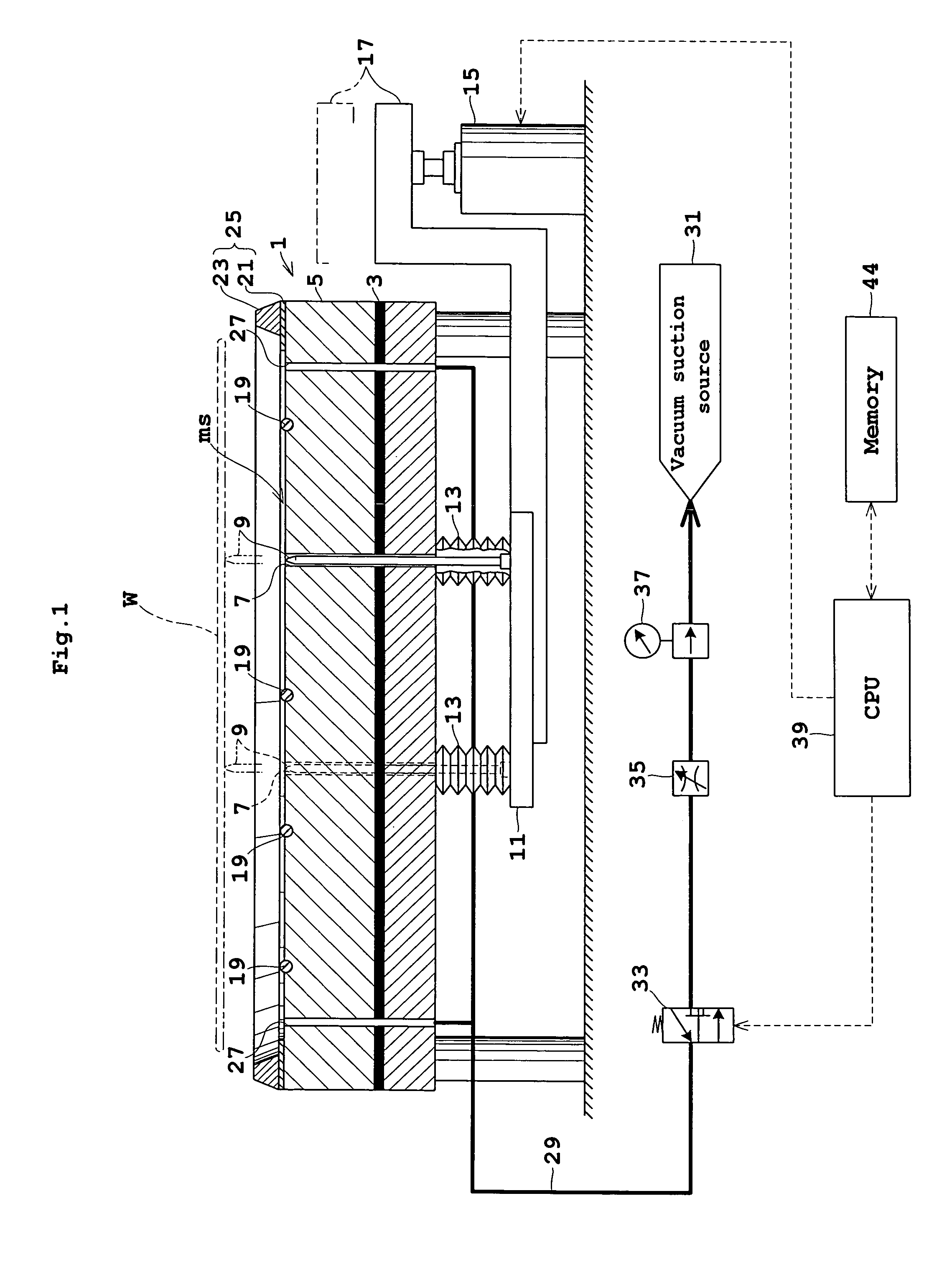
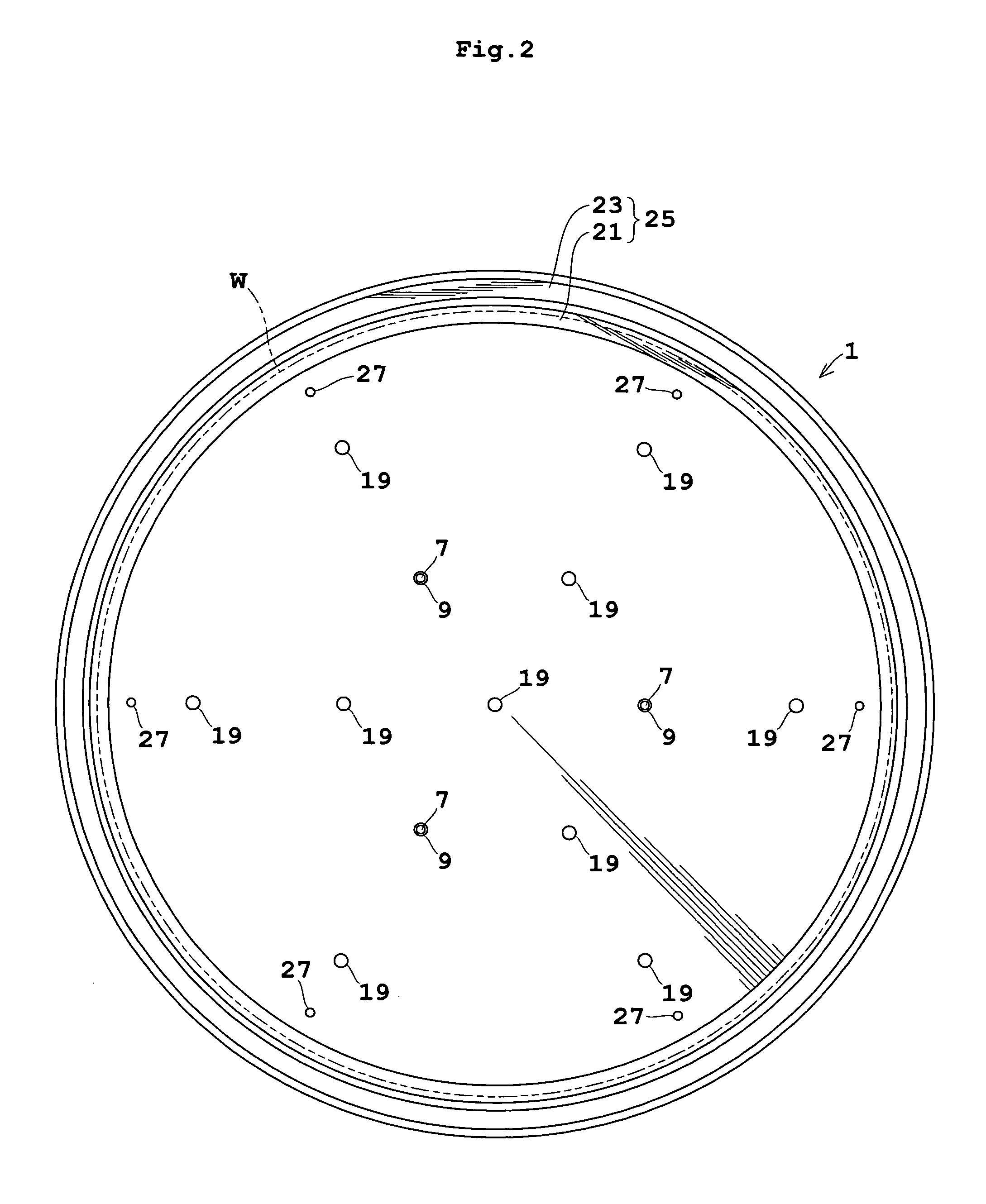
[0043]FIG. 1 is a view in vertical section showing an outline of a substrate heat treatment apparatus in Embodiment 1. FIG. 2 is a plan view of the apparatus shown in FIG. 1. FIG. 3 is an enlarged view in vertical section of a bake plate.

[0044]A bake plate 1 for supporting a substrate or wafer W on an upper surface thereof has a heating element 3 such as a mica heater mounted in a lower portion thereof. A heat transfer portion 5 between the heating element 3 and the upper surface of bake plate 1 has a plurality of heat pipes, not shown, embedded therein. Cooling grooves, not shown, are formed between the heat pipes for circulating a cooling fluid.

[0045]The bake plate 1 has three perforations 7 extending from the upper surface to the lower surface. These perforations 7 are formed in positions corresponding to the apexes of an equilateral triangle in plan view, each having a support pin 9...

embodiment 2

[0059]Next, Embodiment 2 of this invention will be described with reference FIG. 8. FIG. 8 is a view in vertical section showing an outline of a substrate heat treatment apparatus in Embodiment 2. In the following description, like reference numerals are used to identify like parts which are the same as in Embodiment 1 and will not particularly be described.

[0060]Embodiment 2 relates to an improvement made in the upper surface of bake plate 1A.

[0061]Specifically, the upper surface of bake plate 1A, and more particularly the upper surface of heat transfer portion 5A inwardly of the seal assembly 25, is recessed in a shape of shallow concave around the center. When the wafer W is curved to have the central part bulging downward from the periphery (bowl-like curvature), the central part may be drawn first, with only insufficient suction acting on the periphery. The recessed shape of the upper surface of bake plate 1A allows the periphery of wafer W to be fully drawn. Thus, regardless o...

embodiment 3

[0062]Next, Embodiment 3 of this invention will be described with reference FIG. 9. FIG. 9 is an enlarged view in vertical section of a portion of a substrate heat treatment apparatus in Embodiment 3. Like reference numerals are used to identify like parts which are the same as in Embodiment 1 described hereinbefore, and will not particularly be described.

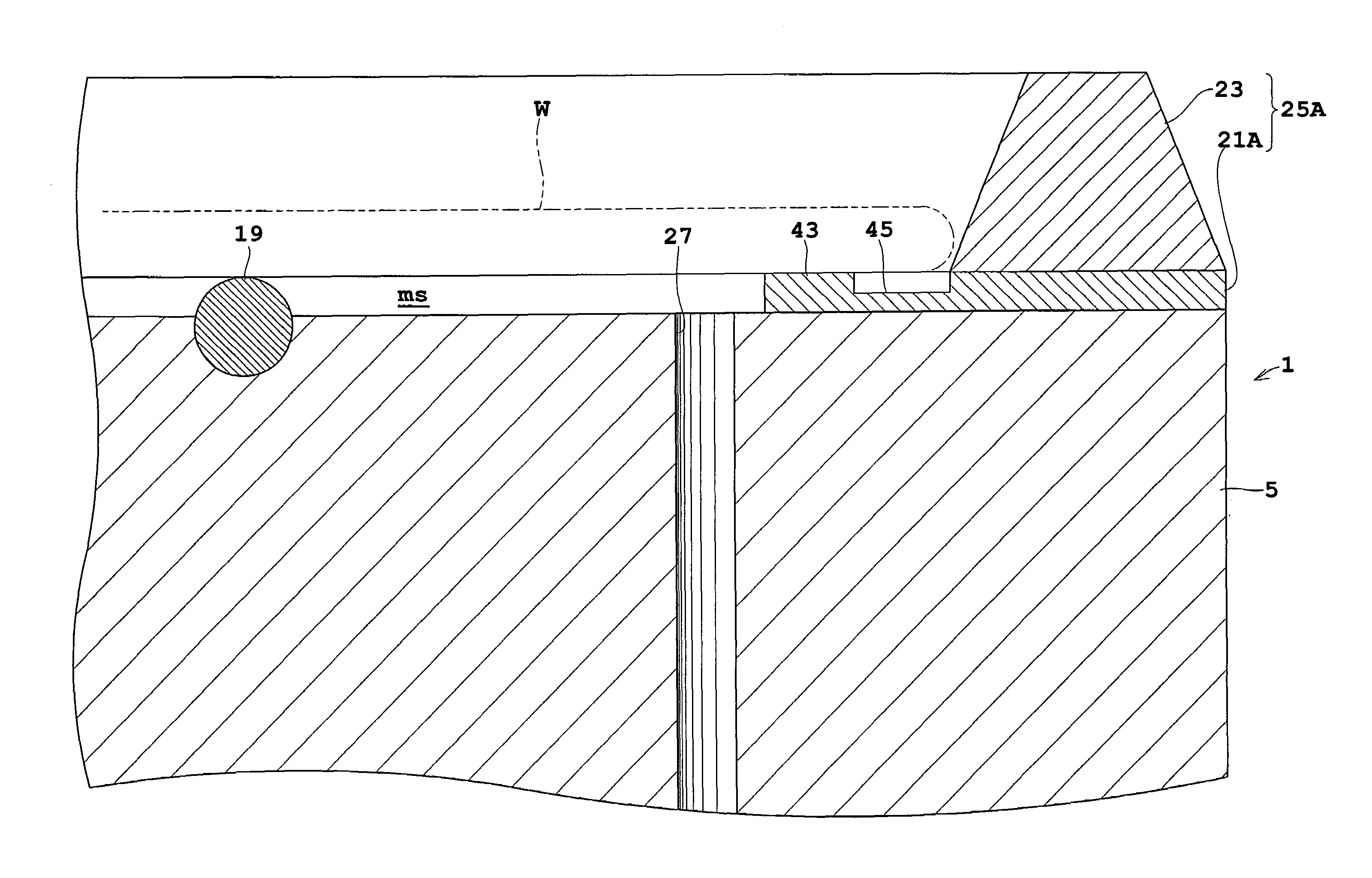
[0063]Embodiment 3 is different from Embodiments 1 and 2 in the construction of a seal assembly 25A.

[0064]Specifically, the seal assembly 25A includes a support portion 21A and a regulator 23. The support portion 21A has a contact portion 43 and a groove 45. The contact portion 43 has an inside diameter slightly smaller than the outside diameter of wafer W, and an upper surface thereof contactable with a portion of the lower surface of wafer W slightly inward from the edge. The groove 45 is located outwardly of the contact portion 43 and does not contact the lower surface of wafer W.

[0065]When the wafer W is placed in the substrate...


PUM

PropertyMeasurementUnit
timeaaaaaaaaaa
diameteraaaaaaaaaa
shapeaaaaaaaaaa

Abstract

A substrate heat treatment apparatus for heat-treating a substrate includes a bake plate having projections on an upper surface thereof, a seal unit disposed peripherally of the upper surface of the bake plate for closing a lateral area of a minute space formed between a lower surface of the substrate and the upper surface of the bake plate when the substrate is placed on the bake plate, and exhaust bores for exhausting gas from the minute space. The substrate placed on the bake plate is heat-treated in a state of the gas exhausted from the minute space through the exhaust bores.

Description

BACKGROUND OF THE INVENTION[0001](1) Field of the Invention[0002]This invention relates to a substrate heat treatment apparatus for heat-treating substrates such as semiconductor wafers and glass substrates for liquid crystal displays (hereinafter simply called substrates). More particularly, the invention relates to a technique for heat-treating a substrate slightly spaced from a bake plate instead of being in contact with the plate.[0003](2) Description of the Related Art[0004]A conventional apparatus of the type noted above has a bake plate variable in temperature, and three balls arranged on an upper surface of the bake plate to be located at apexes of an equilateral triangle in plan view (as disclosed in Japanese Unexamined Patent Publication No. 2000-193376, for example). With this apparatus, a substrate placed on the bake plate is supported at a lower surface thereof by the three balls, so that the entire lower surface is separated by a minute space from the bake plate instea...

Claims


Application Information

Patent Timeline
Patent Type & Authority Patents(United States)
IPC IPC(8): H05B3/68C23C16/00
CPCF27B5/04F27B17/0025F27D3/0084H01L21/67109H01L21/67126H01L21/68742H01L21/6875H01L21/68735H01L21/324
Inventor MORITA, AKIHIKOGOTO, SHIGEHIROMATSUCHIKA, KEIJI
Owner DAINIPPON SCREEN MTG CO LTD
Why Eureka
Try Eureka