Magnetic shields and instruments for measuring biomagnetic fields

Inactive Publication Date: 2008-10-07
HITACHI LTD
View PDF15 Cites 2 Cited by
  • Summary
  • Abstract
  • Description
  • Claims
  • Application Information

AI Technical Summary

Benefits of technology

[0013]The conventional magnetically shielded room which uses multilayered permalloy must surround the entire apparatus by a ferromagnetic substance. Its volume and weight are increased to require a large installation place. The magnetically shielded room for electronic drawing equipment installed in a clean room needs, in its inside, air-conditioning equipment to increase the cost.
[0016]An object of the present invention is to provide a magnetic shield which can shield an external magnetic field vertical to an axis of a tubular magnetic shield with open ends on at least one end and in the direction vertical to the axis, and an instrument for measuring a biomagnetic field using the same. Another object of the present invention is to provide a relative arrangement method of a magnetic shield and an instrument for measuring a biomagnetic field, and a relative arrangement method of a magnetic shield and a measuring instrument using a charged particle beam.
[0020]The magnetic shield according to the present invention can shield, not only an external magnetic field parallel to the axis, but also an external magnetic field vertical to the axis. This can reduce magnetic field noise in the cylindrical magnetic shield as compared with the case that there is one superconducting loop at each open end. It is possible to realize an open-type, small, lightweight magnetic shield.
[0021]The magnetic shield according to the present invention does not use large superconductors so that a cryostat is simple. The superconducting loops and the cylindrical magnetic shield are manufactured separately. These are combined to realize a simple construction.

Problems solved by technology

The axial length about twice larger than its diameter is necessary, thereby imposing the problem of shortening in the axial length.

Method used


Image

  • Magnetic shields and instruments for measuring biomagnetic fields
  • Magnetic shields and instruments for measuring biomagnetic fields
  • Magnetic shields and instruments for measuring biomagnetic fields

Examples


embodiment 1

(Embodiment 1)

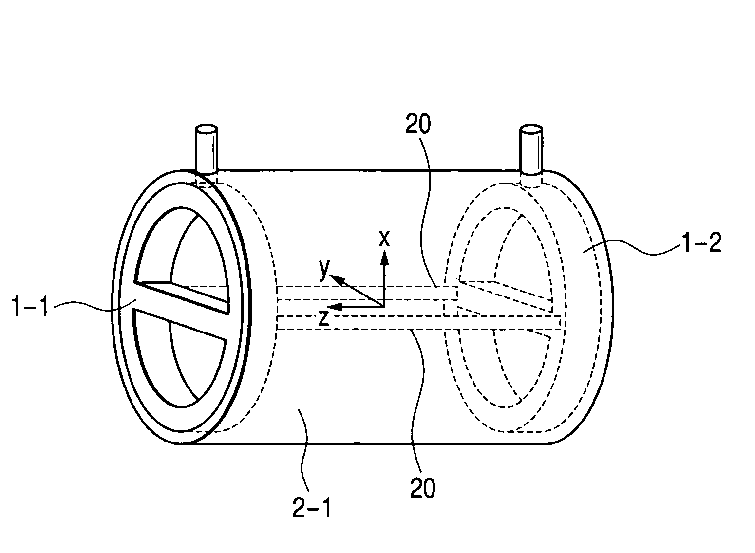
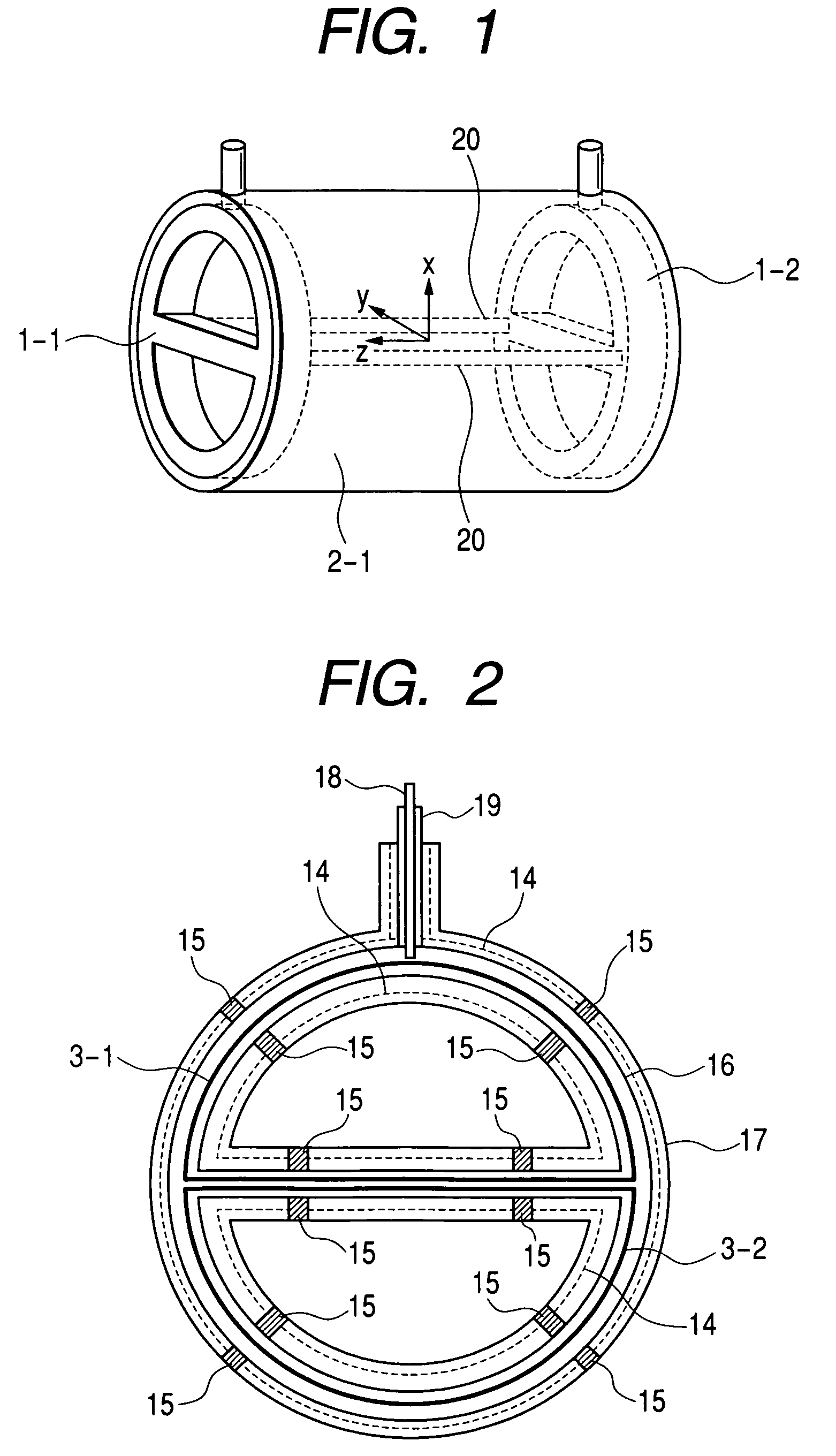
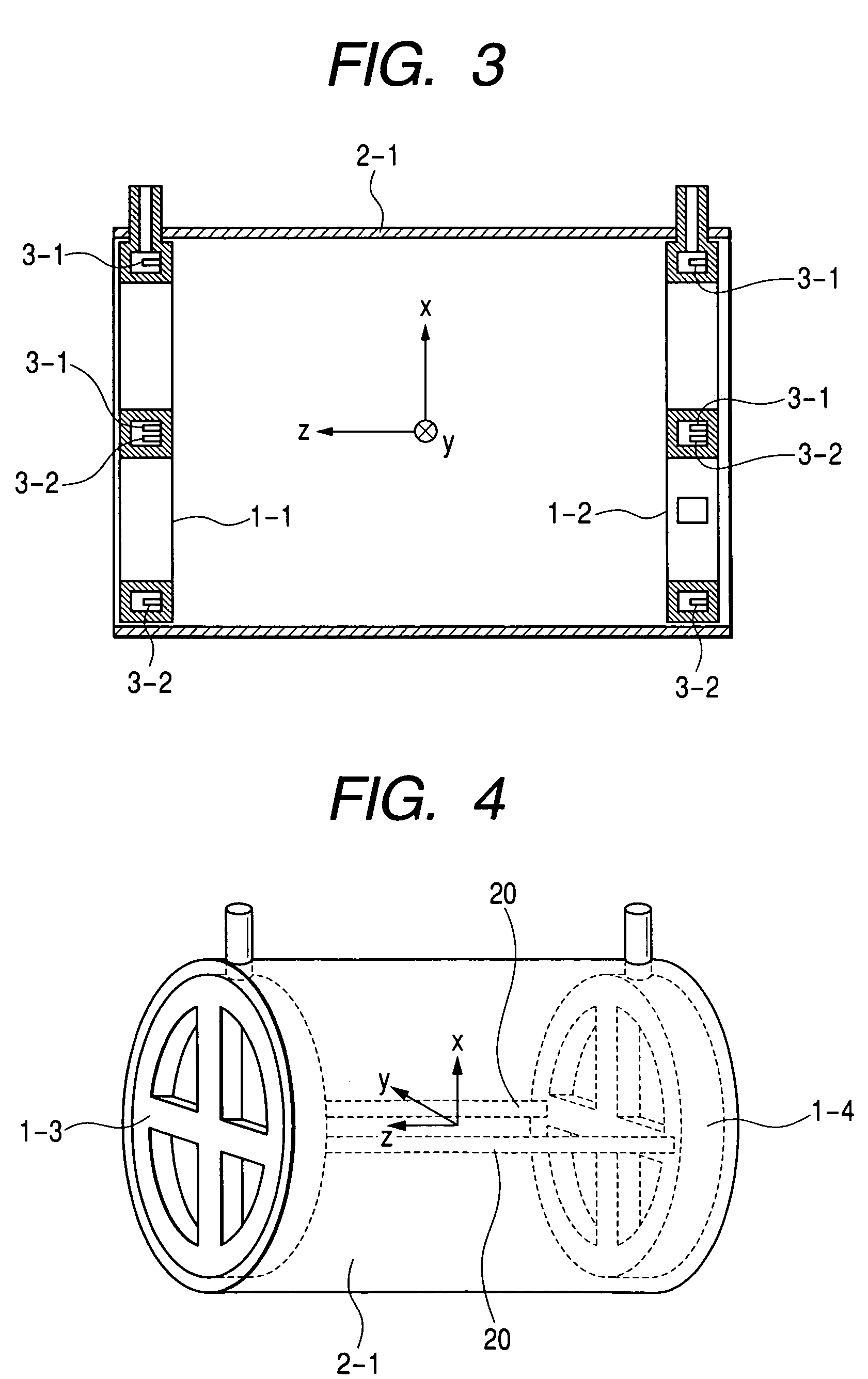
[0044]FIG. 1 is a perspective view showing the construction of a magnetic shield of Embodiment 1 of the present invention. FIG. 2 is a cross-sectional view of a superconducting loop container 1 of Embodiment 1 of the present invention and is a cross-sectional view of a plane parallel to yz shown in FIG. 1 passing through the superconducting loops. FIG. 3 is a cross-sectional view of the magnetic shield of Embodiment 1 of the present invention and is a cross-sectional view of xz-plane shown in FIG. 1.

[0045]The magnetic shield has a cylindrical ferromagnetic substance 2-1 having openings on both ends and two superconducting loops housed in the respective insides of superconducting loop containers 1-1, 1-2. The superconducting loops are constructed of high critical temperature superconducting wire. The two superconducting loops have semicircle shapes and are arranged in x-direction to be symmetrical with respect to an axis of the cylindrical ferromagnetic substance 2-1.

[0...

embodiment 2

(Embodiment 2)

[0050]FIG. 4 is a perspective view showing the construction of a magnetic shield of Embodiment 2 of the present invention. The magnetic shield has a cylindrical ferromagnetic substance 2-1 having openings on both ends, and four superconducting loops housed in the respective insides of superconducting loop containers 1-3, 1-4. The superconducting loops are constructed of high critical temperature superconducting wire. The four superconducting loops have quarter circle shapes and are arranged in x and y-directions so as to be symmetrical with respect to an axis of the cylindrical ferromagnetic substance 2-1. The superconducting loop containers 1-3, 1-4 are arranged in the insides near both open ends of the cylindrical ferromagnetic substance 2-1 with supports 20. The superconducting loop containers 1-3, 1-4 may be arranged in the outsides near both open ends of the cylindrical ferromagnetic substance 2-1 with the supports 20. The superconducting loops are arranged to be ...

embodiment 3

(Embodiment 3)

[0053]A magnetic shield of Embodiment 3 of the present invention has a construction such that one or more cylindrical ferromagnetic substances are arranged on the outside of the magnetic shield of Embodiment 1 or 2.

[0054]FIG. 5 is a cross-sectional view showing the construction of a magnetic shield of Embodiment 3 of the present invention and a cross-sectional view of xz plane. In the magnetic shield of Embodiment 3, a cylindrical ferromagnetic substance 2-2 coaxial with the axis of the cylindrical ferromagnetic substance 2-1 explained in FIGS. 1, 2 and 3 is arranged on the outside of the cylindrical ferromagnetic substance 2-1. In the example shown in FIG. 5, the length in the direction of an axis of the cylindrical ferromagnetic substance 2-2 is larger than that of the cylindrical ferromagnetic substance 2-1 and may be almost the same. In addition, in the example shown in FIG. 5, one cylindrical ferromagnetic substance 2-2 having openings on both ends is used. A plur...


PUM


Abstract

There is provided a magnetic shield which can shield external magnetic fields in the direction of an axis of a tubular magnetic shield and in the direction vertical to the axis. A magnetic shield has a cylindrical ferromagnetic substance 2-1 having openings on both ends and two superconducting loops housed in the respective insides of superconducting loop containers 1-1, 1-2. The superconducting loops are constructed of high critical temperature superconducting wire. The two superconducting loops have semicircle shapes and are arranged in x-direction so as to be symmetrical with respect to an axis of the cylindrical ferromagnetic substance 2-1. The superconducting loop containers 1-1, 1-2 are arranged in the insides near both open ends of the cylindrical ferromagnetic substance 2-1 with supports 20. The superconducting loops are arranged to be vertical to the axis of the cylindrical ferromagnetic substance 2-1. The superconducting loops are cooled by liquid nitrogen or a refrigerator. A lightweight, small magnetic shield having high operability can be realized.

Description

[0001]This application claims foreign priority based on Japanese Patent application No. 2002-346775, filed Nov. 29, 2002, the content of which is incorporated herein by reference in its entirety.CROSS-REFERENCE TO RELEVANT APPLICATION[0002]The disclosure of the patent application, Ser. No. 10 / 442,956, Filed on May 22, 2003, pending in THE UNITED STATES Patent AND TRADEMARK OFFICE, has been incorporated by reference into the present application.FIELD OF THE INVENTION[0003]The present invention relates to a magnetic shield shielding environment magnetic field noise and an instrument for measuring a biomagnetic field using the same.BACKGROUND OF THE INVENTION[0004]A magnetic shield is used for electronic drawing equipment using an electron beam and an instrument for measuring a biomagnetic field which measures a weak magnetic field generated from a living body. In general, a magnetically shielded room is constructed as a closed room formed by fastening plates of permalloy of an Fe-Ni a...

Claims


Application Information

Patent Timeline
IPC IPC(8): G01R33/035G01R33/02A61B5/04A61B5/05G01R33/025H01L39/04
CPCA61B5/04005G01R33/025Y10S505/846A61B5/242
Inventor SEKI, YUSUKESUZUKI, DAISUKEOGATA, KUNIOMITSUKADA, KEIJI
Owner HITACHI LTD
Why Eureka
Try Eureka