Simplified article for carbon monoxide removal

a carbon monoxide and article technology, applied in the direction of physical/chemical process catalysts, combustible gas purification/modification, separation processes, etc., can solve the problem of reducing the efficiency of carbon monoxide removal

Inactive Publication Date: 2006-10-19
BASF CORP
View PDF9 Cites 1 Cited by
  • Summary
  • Abstract
  • Description
  • Claims
  • Application Information

AI Technical Summary

Benefits of technology

[0003] Fuel cells directly convert chemical energy into electricity thereby eliminating the mechanical process steps that limit thermodynamic efficiency, and have been proposed as a power source for many applications. The fuel cell can be two to three times as efficient as the internal combustion engine with little, if any, emission of primary pollutants such as carbon monoxide, hydrocarbons and nitric oxides. Fuel cell-powered vehicles which reform hydrocarbons to power the fuel cell generate less carbon dioxide (green house gas) and have enhanced fuel efficiency.
[0013] Lowering levels of carbon monoxide below 10 ppm from input gas streams that contain higher levels of carbon monoxide (e.g., 0.2 to 2% by volume) by preferential oxidation processes typically requires at least two catalyst stages. These higher levels of carbon monoxide are frequently observed in reformate gases received from water-gas shift reactors. In practice the treatment of such levels of carbon monoxide in hydrogen streams is conducted by treatment with a first preferential oxidation stage having a first oxygen input to produce an intermediate gas stream, which is then treated in a second preferential oxidation stage with a second injection of oxygen. The use of two preferential oxidation stages increases the volume and weight of the fuel processor. Moreover, the use of two oxygen injections is unfavorable from the standpoint that more hydrogen is inevitably oxidized in addition to the intended oxidation of carbon monoxide.
[0019] Continuing improvements in the design of fuel processors, and in particular, to the design of the apparatus for the removal of the residual carbon monoxide from the hydrogen stream that is ultimately fed to the fuel cell, are desirable. Improvements to the carbon monoxide removal articles that optimize factors such as high carbon monoxide conversions, carbon monoxide selectivity, simplicity of design and minimization of reactor volumes / weights are especially desirable. SUMMARY OF THE INVENTION

Problems solved by technology

More complete removal of carbon dioxide from the process stream using solely the water-gas shift reaction however, is difficult to achieve due to both kinetic and equilibrium limitations.
An undesirable side reaction in this method is therefore the oxidation of hydrogen according to the following reaction:
Nevertheless, it may be difficult to achieve threshold levels of carbon monoxide below 100 ppm using only a single stage platinum-based catalyst due to the reverse water-gas shift activity exhibited by platinum-based catalysts.
These conditions contribute to the detrimental formation of carbon monoxide, and thwart efforts to more completely remove carbon monoxide from the hydrogen gas stream.
Moreover, the use of two oxygen injections is unfavorable from the standpoint that more hydrogen is inevitably oxidized in addition to the intended oxidation of carbon monoxide.
In addition, methanation of carbon dioxide can lead to a runaway reaction resulting in high temperatures that can damage the catalyst beds.

Method used


Image

  • Simplified article for carbon monoxide removal
  • Simplified article for carbon monoxide removal
  • Simplified article for carbon monoxide removal

Examples


example 1

Preparation of 5 wt. % Ruthenium on Alumina Washcoat

[0089] An aqueous ruthenium nitrosyl nitrate solution (52.8 g) was diluted with deionized water to provide a 73 mL volume of solution. This solution was used to impregnate 100 g of gamma alumina powder using an incipient wetness impregnation technique. After mixing well, the powder was dried at 120° C. for two hours, and then calcined at 250° C. for two hours. The powder was slurried with water to form the washcoat.

example 2

Preparation of a Zoned Catalyst Article, Article A (Prox Catalyst Zone / Dual Catalyst Zone)

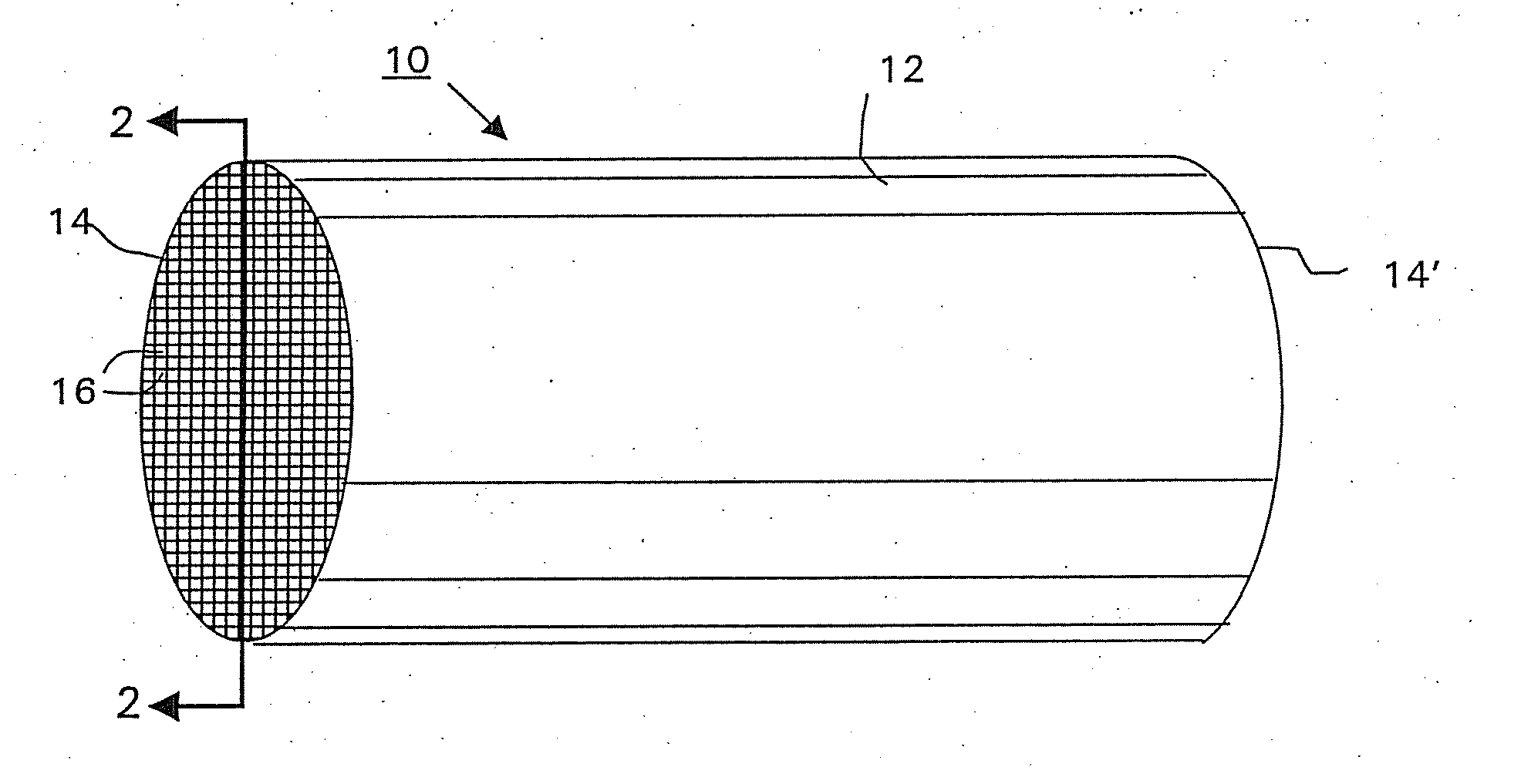
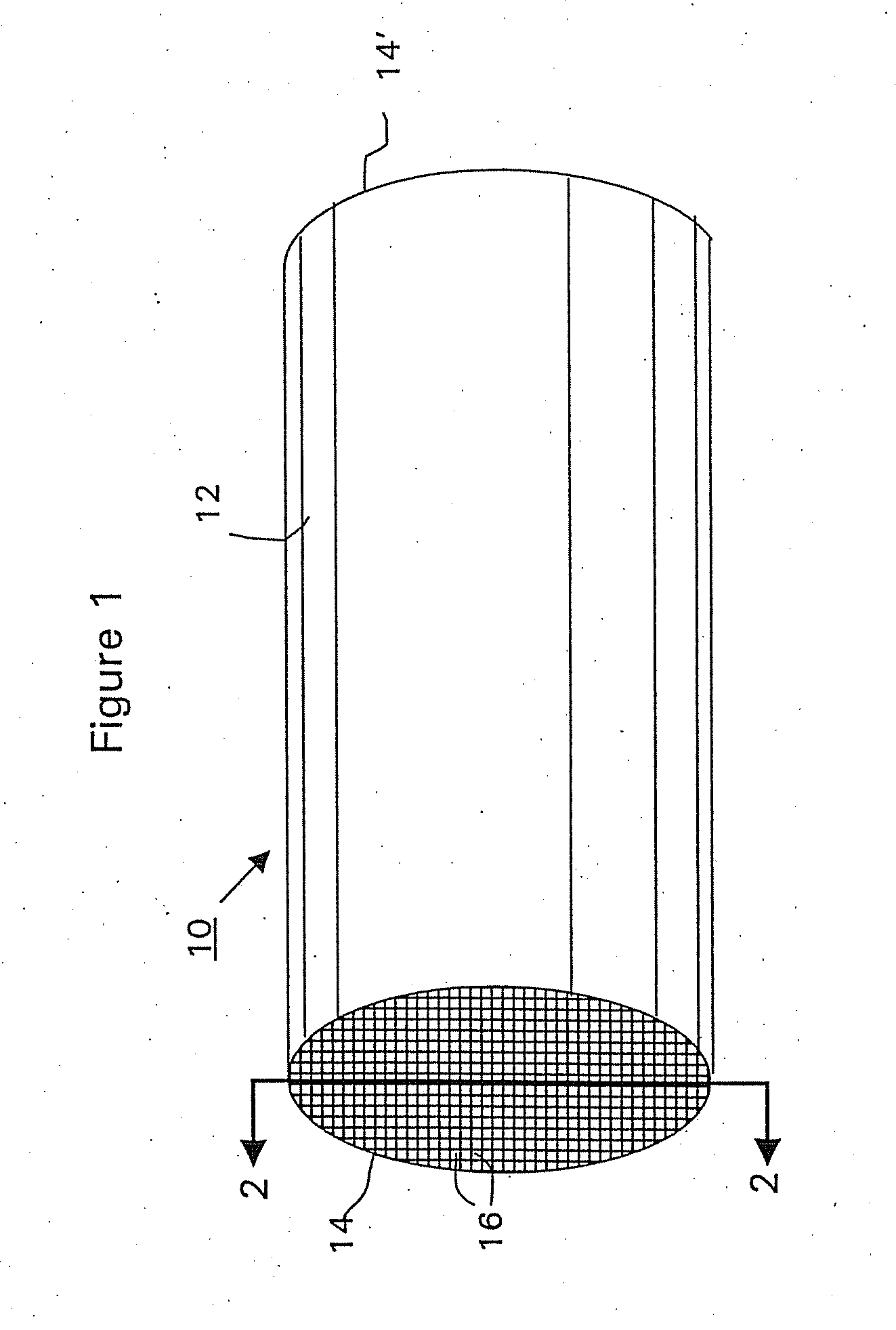
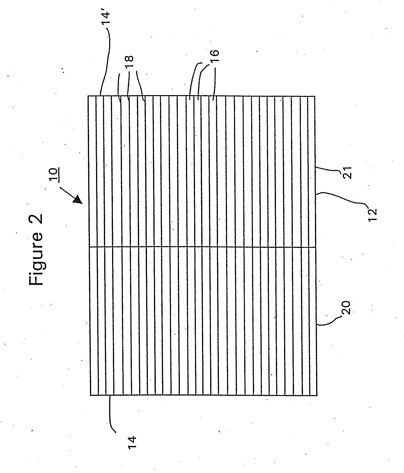
[0090] A commercially available, monolithic catalyst coated along the entire axial length with a washcoat having approximately 5 wt. % platinum and about 0.3 wt. % iron on an alumina support (Selectra.™. PROX catalyst (Engelhard Corp. Iselin N.J.) was used as the starting workpiece. The ceramic monolith substrate contained 400 cells per square inch (cpsi). The monolith substrate was dipped into the 5% Ru / alumina washcoat of Example 1 to a depth of 50% of the substrate's axial length to form the second (top layer). The washcoat loading of the second layer was 2 g / in3 based on the coated volume (i.e., the axial segment of the monolith substrate that was coated with the ruthenium-containing washcoat). The excess slurry was removed by blowing air through the channels of the monolith. The catalyst was then dried at 120° C., and calcined at 250° C. in air.

[0091] The ruthenium layer in the article w...

example 3

Preparation of a Reference Bilayer Catalyst Article, Article B, Having a First Layer Containing a Prox Catalyst and Second Layer Containing a Methanation Catalyst

[0093] A monolith catalyst article was prepared identically to Article A of Example 2, except that the ruthenium-containing washcoat was coated overlaying the first layer over the entire axial length of the monolith substrate. The washcoat loading of the second layer was 1 g / in3 based on the coated volume. This catalyst article is designated as “Article B”.

[0094] It is noted that Article B and Article A of Example 2 contained the same loading of ruthenium washcoat based on the entire volume of the substrate. In addition, the total platinum group loading for both Articles A and B was the same.


PUM

PropertyMeasurementUnit
temperatureaaaaaaaaaa
temperaturesaaaaaaaaaa
particle sizesaaaaaaaaaa

Abstract

Provided are improved carbon monoxide removal articles and processes for treating hydrogen gas streams to achieve very low threshold levels of carbon monoxide. The articles have a substrate with an inlet end, an outlet end, a length extending between the inlet end to the outlet end, wall elements and a plurality of cells defined by the wall elements. A first layer is deposited on the wall elements from the inlet end and extending at least partially toward the outlet end. The first layer has a preferential carbon monoxide oxidation catalyst. A second layer contains a methanation catalyst, and is deposited on at least part of the first layer from the outlet end. The second layer has a length that is about 10-70% of the substrate length.

Description

RELATED APPLICATION [0001] This application is a continuation of and claims the benefit of U.S. patent application Ser. No. 10 / 236,085, which was filed Sep. 6, 2002, and entitled SIMPLIFIED ARTICLE FOR CARBON MONOXIDE REMOVAL, the entirety of which is hereby incorporated by reference.[0002] The present invention relates to articles and methods for the removal of carbon monoxide (CO) from a hydrogen gas stream. The invention also relates to apparatus (fuel processors) that incorporate the carbon monoxide removal articles that supply hydrogen to a fuel cell, particularly to a proton exchange membrane (PEM) fuel cell. [0003] Fuel cells directly convert chemical energy into electricity thereby eliminating the mechanical process steps that limit thermodynamic efficiency, and have been proposed as a power source for many applications. The fuel cell can be two to three times as efficient as the internal combustion engine with little, if any, emission of primary pollutants such as carbon mo...

Claims


Application Information

Patent Timeline
Patent Type & Authority Applications(United States)
IPC IPC(8): C07C27/06C01B3/38B01J19/24B01J23/46B01J23/89B01J35/00B01J35/04B01J37/02C01B3/58
CPCB01J19/2485B01J23/462B01J23/8906B01J35/0006B01J35/04C01B2203/047B01J2208/025C01B3/583C01B3/586C01B2203/044C01B2203/0445B01J37/0244C01B3/58B01J23/46B01J23/89B01J35/00
Inventor SHORE, LAWRENCE
Owner BASF CORP
Why Eureka
Try Eureka