Sensor

Inactive Publication Date: 2008-10-14
ROBERT BOSCH GMBH
View PDF16 Cites 35 Cited by
  • Summary
  • Abstract
  • Description
  • Claims
  • Application Information

AI Technical Summary

Benefits of technology

[0008]According to an advantageous embodiment of the present invention, the housing is formed by an internal protective tube surrounding the end of the sensor element on the measuring gas side, the internal protective tube being in turn concentrically surrounded by the protective tube. One end of the internal protective tube facing the protective sleeve carries a single-piece flange, which is joined to the two flanges on the protective tube and on the protective sleeve and is secured on the sealing seat. This arrangement replaces the double protective tube for the end section of the sensor element on the measuring gas side, which is often used in exhaust gas sensors, and the function of the housing, a component being made

Problems solved by technology

This reduces both the investment outlay and the ma

Method used


Image

  • Sensor
  • Sensor
  • Sensor

Examples


Embodiment Construction

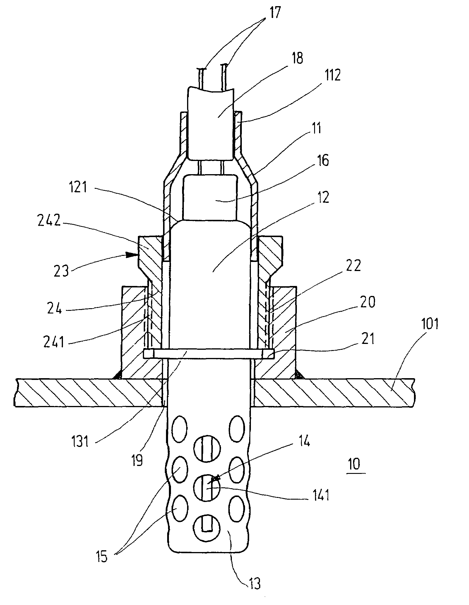
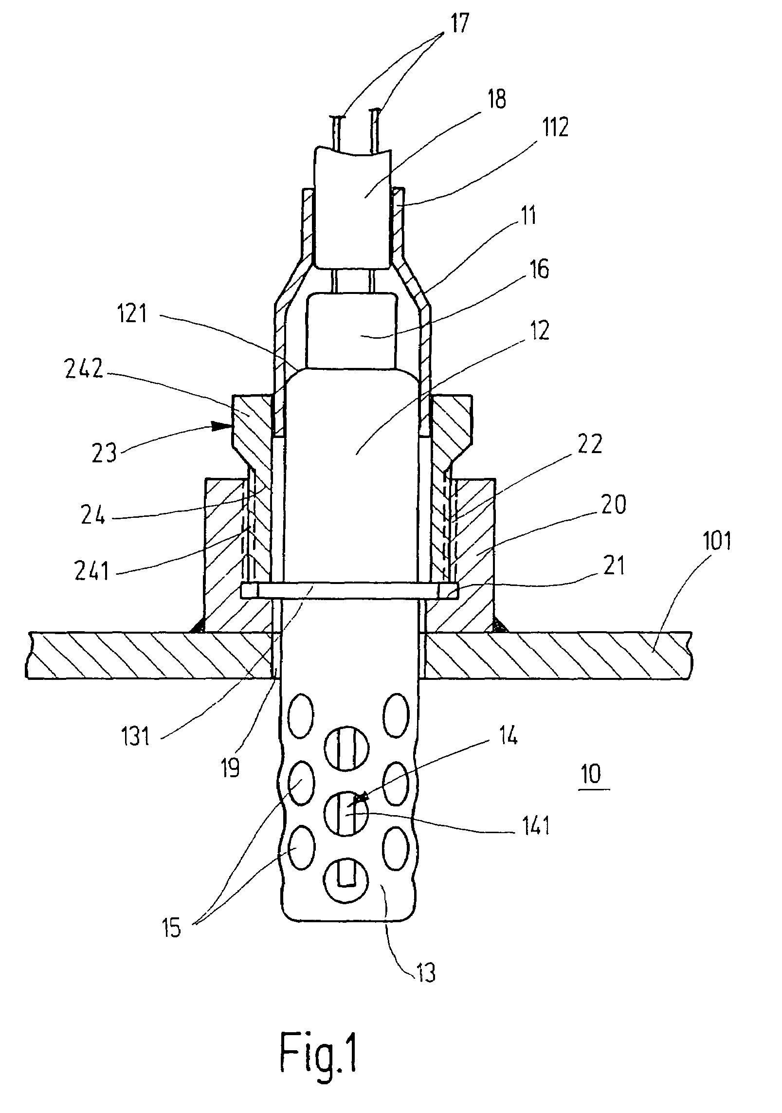
[0011]The exhaust gas sensor shown in FIG. 1 is depicted in its installed position in an exhaust pipe 10 of a motor vehicle as an exemplary embodiment of a generic sensor for determining a physical property of a measuring gas, which sensor is used as a lambda sensor for determining the oxygen concentration in the exhaust gas of internal combustion engines. The exhaust gas sensor has a sensor element 14, which is surrounded by an enclosure composed of a protective sleeve 11, a tubular housing 12, and a protective tube 13. Sensor element 14, only an end section 141 of which is visible in FIG. 1 on the measuring gas side through gas passage holes 15 in protective tube 13, is depicted in its entirety in FIG. 6. As FIG. 6 shows, the other, connection side, end section 142 of sensor element 14 is electrically connected to connecting cables 17 via a connecting plug 16. In the exemplary embodiments of FIGS. 1 through 5, connecting cables 17 are surrounded by a sheathing tube 18. Protective ...


PUM

PropertyMeasurementUnit
Diameteraaaaaaaaaa
Electrical resistanceaaaaaaaaaa
Areaaaaaaaaaaa

Abstract

A sensor for determining a physical property such as the concentration of a gas component or the temperature of a measuring gas, e.g., the exhaust gas of internal combustion engines, has a sensor element which is secured in a housing and is surrounded at an end section on the measuring gas side by a protective tube and surrounded at an end section on the connection side by a protective sleeve, and also has a radially projecting flange for securing the sensor on a sealing seat formed on a measuring gas duct. To reduce manufacturing costs, the flange is molded onto the protective tube as one piece. The protective tube is manufactured as a deep-drawn part, and a trimming edge remaining after deep drawing on the end side is used as a securing flange.

Description

FIELD OF THE INVENTION[0001]The present invention relates to a sensor for determining a physical property such as the concentration of a gas component or the temperature of a measuring gas, e.g., the exhaust gas of internal combustion engines.BACKGROUND INFORMATION[0002]Published German patent document DE 43 18 107 describes a sensor for detecting gases flowing in a gas duct, in which the housing that accommodates the sensor element is designed as a tubular metal housing having a longitudinal bore. The outer periphery of the metal housing has a single-piece peripheral flange, which is used for securing the metal housing on a sealing seat formed on the gas duct. A central section of the sensor element is inserted centrally into the metal housing and is secured via a sealing system which presses against both the sensor element and the bore wall of the longitudinal bore, an end section on the measuring gas side and an end section on the connection side of the sensor element projecting ...

Claims


Application Information

Patent Timeline
IPC IPC(8): G01N27/26G01M15/10G01N27/407
CPCG01N27/4077G01N27/4078Y10T29/49007F01N2560/02F01N13/008
Inventor WEYL, HELMUTWILDE, JUERGENPESCH, ANDREAS
Owner ROBERT BOSCH GMBH
Why Eureka
Try Eureka