Vehicle pinion shaft support system

a technology of pinion shaft and support system, which is applied in the direction of gearing, heat treatment equipment, furnaces, etc., can solve the problems of increasinggenerating vibration and looseness between the pinion shaft and the tapered roller, and reducing the value of the pre-load. , to achieve the effect of reducing the running cost of the vehicle pinion shaft support system, reducing the initial stage of operation, and reducing the running cost of the vehicl

Inactive Publication Date: 2008-10-14
JTEKT CORP
View PDF24 Cites 7 Cited by
  • Summary
  • Abstract
  • Description
  • Claims
  • Application Information

AI Technical Summary

Benefits of technology

[0016]According to the first aspect of the invention, since the inner race has the large rib face having the recessed surface shape on which the large-diameter end faces of the tapered rollers slide and when assuming that the surface roughness of the large-diameter end faces is σ1 [μmRa] and the surface roughness of the large rib face is σ2 [μmRa], σ1 is 0.025 or more and (σ12+σ22)1 / 2 is 0.17 [μmRa] or less, the formation of an oil film between the large-diameter end faces and the large collar portion is facilitated. Consequently, the value of the torque needed to drive the tapered roller bearings can be reduced largely, thereby making it possible to reduce remarkably the running costs of the vehicle pinion shaft support system.
[0056]Consequently, since the pre-load to be applied to the tapered roller bearings at the initial setting of the vehicle pinion shaft support system can be set to a lower value than one set in the conventional system, which is a pre-load which realizes an appropriate support rigidity from the beginning, the torque in particular at the initial stage of an operation can be reduced, thereby making it possible to reduce the running costs of the vehicle pinion shaft support system. In addition, the support rigidity of the pinion shaft by the tapered roller bearings can also be maintained at a desirable value over long period of time, whereby the generation of looseness between the tapered roller bearings and the pinion shaft can be prevented, thereby making it possible to extend the life of the vehicle pinion shaft support system remarkably.

Problems solved by technology

In the conventional vehicle pinion shaft support system, however, in the event that the initial pre-load value is set high with a view to increasing the support rigidity of the pinion shaft, a torque needed to drive the two tapered roller bearings is increased, leading to a problem that the running costs of the vehicle pinion shaft support system are, in turn, increased.
On the other hand, in the event that the initial pre-load is set to a proper value or a value that is lower than the proper value, the value of the pre-load is decreased by a wear generated mainly between the large-diameter end faces of the tapered rollers and the large rib face of the inner races whereby the support rigidity of the pinion shaft by the tapered rollers becomes lower than a predetermined value, leading to a problem that vibration and looseness are generated between the pinion shaft and the tapered rollers.

Method used


Image

  • Vehicle pinion shaft support system
  • Vehicle pinion shaft support system
  • Vehicle pinion shaft support system

Examples


Embodiment Construction

[0060]Hereinafter, the invention will be described in detail based on an embodiment thereof.

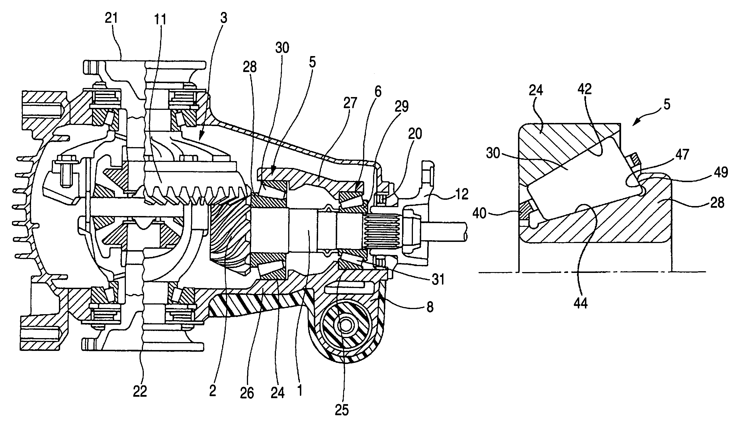
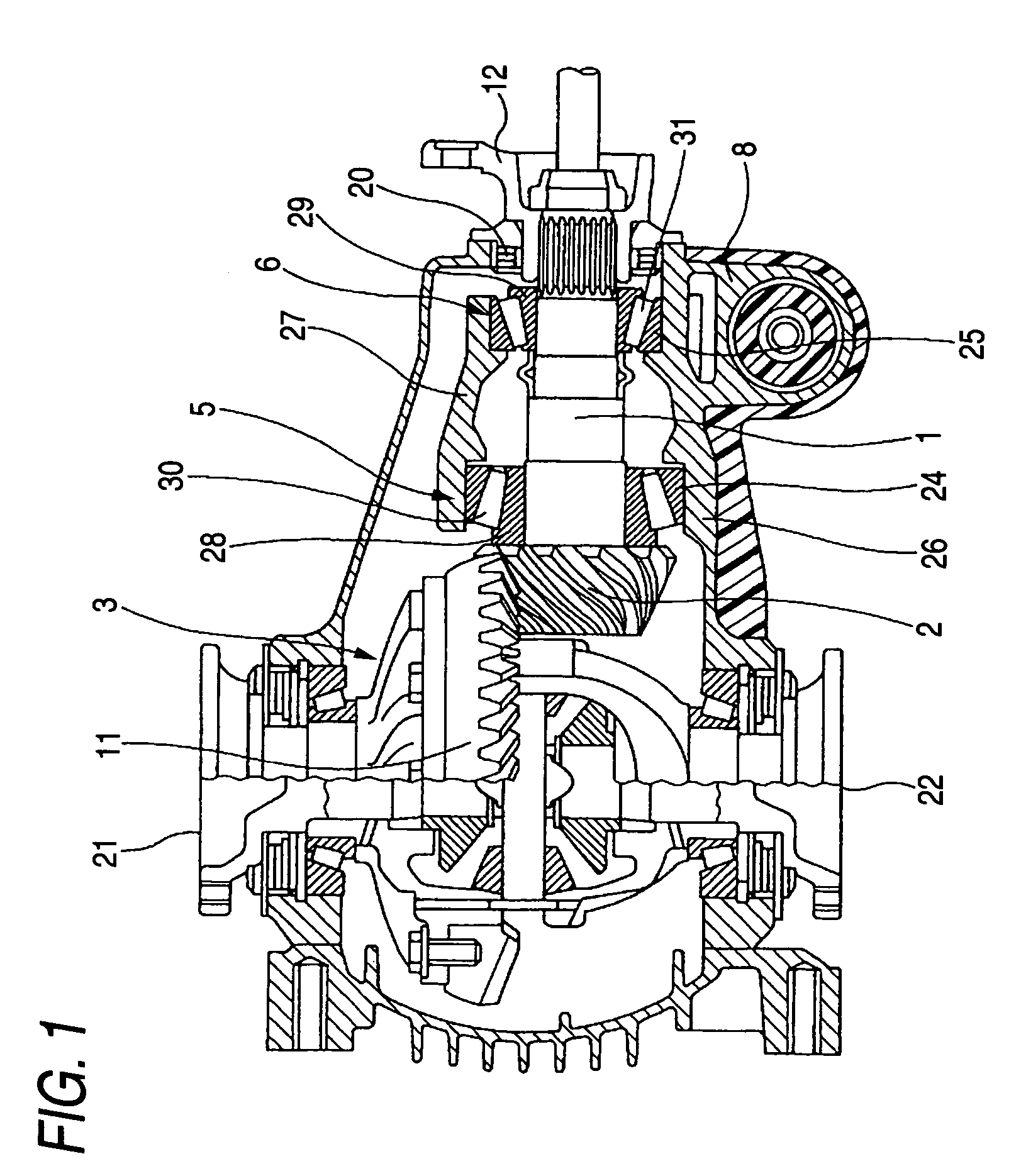
[0061]FIG. 1 is a sectional view of a differential gearbox which is an example to which a vehicle pinion shaft support system of the invention is applied.

[0062]This differential gearbox includes a pinion shaft 1, a differential mechanism 3, a primary tapered roller bearing 5, which is disposed on an outer circumference of the pinion shaft 1 at an end thereof which lies to a side of the differential mechanism 3, a secondary tapered roller bearing 6, which is disposed on the outer circumference of the pinion shaft 1 at an opposite end to the end thereof which lies to the side of the differential mechanism 3, and a casing 8 which accommodates therein the pinion shaft 1, the differential mechanism 3, the primary tapered roller bearing 5 and the secondary tapered roller bearing 6.

[0063]A pinion gear 2 is formed at an end portion of the pinion shaft 1 which lies to the side of the differential mech...


PUM

PropertyMeasurementUnit
diameteraaaaaaaaaa
diameteraaaaaaaaaa
temperatureaaaaaaaaaa

Abstract

There are provided tapered roller bearings which support a pinion shaft. Inner races have large rib faces each having a recessed surface shape on which large-diameter end faces of tapered rollers slide. The surface roughness of the large-diameter end face is σ1 [μmRa] is 0.025 or more. In addition, assuming the surface roughness of the large rib face is σ2 [μmRa], (σ12+σ22)1 / 2 is 0.17 [μmRa] or less. The sliding portion of the large-diameter end face and the sliding portion of the large rib face are made of a carburized steel, and the carbon content in a matrix phase in a surface layer portion of each of the sliding portions to a depth of 50 μm from a surface is 0.8 wt % or more, the surface hardness thereof is in the range of Rockwell C63 to 67, and a surface retained austenite amount is set to be 20% or more and 25% or less.

Description

BACKGROUND OF THE INVENTION[0001]The present invention relates to a vehicle pinion shaft support system (pinion shaft supporting device for vehicle or automobile) and more particularly to, for example, a vehicle pinion shaft support system such as used at a differential (differential gear, differential deice etc.) and a transaxle (differential transaxle, transaxle device, transaxle apparatus etc.).[0002]As a conventional vehicle pinion shaft support system, there exists a vehicle pinion shaft support system such as described in JP-A-8-247260 (Patent Document No. 1).[0003]The vehicle pinion shaft support system includes a pinion shaft, two tapered roller bearings which are provided on the pinion shaft in such a manner as to be spaced apart from each other at a predetermined interval and a pinion ring which meshes with the pinion shaft.[0004]Each of the two tapered roller bearings has an inner race, an outer race and tapered rollers disposed between the inner race and the outer race. ...

Claims


Application Information

Patent Timeline
Patent Type & Authority Patents(United States)
IPC IPC(8): F16C33/58F16C19/00F16C33/62C21D1/06C21D1/18C21D9/40C22C38/00F16C19/36F16C33/64F16H57/021F16H57/037F16H57/038F16H57/039
CPCF16C19/364F16C19/505F16C33/36F16C33/62F16C33/64F16H57/021F16H57/037F16H2048/423F16C2240/18F16C2361/61F16C2202/04F16C2240/54
Inventor KAWAGUCHI, TOSHIHIRO
Owner JTEKT CORP
Why Eureka
Try Eureka