Thinners for invert emulsions

a technology of invert emulsion and thinner, which is applied in the direction of fluid removal, borehole/well accessories, chemistry apparatus and processes, etc., can solve the problems of such prior art thinners, problems such as sticking of drill strings, and loss of circulation, so as to enhance the ability of drilling fluid, reduce the viscosity of drilling fluid, and maintain the effect of viscosity

Inactive Publication Date: 2008-10-14
HALLIBURTON ENERGY SERVICES INC
View PDF168 Cites 56 Cited by
  • Summary
  • Abstract
  • Description
  • Claims
  • Application Information

AI Technical Summary

Benefits of technology

[0013]According to the method of the present invention, a compound is added to a water-in-oil or invert emulsion drilling fluid or well service fluid which reduces the viscosity of the drilling fluid or well service fluid at low temperatures or which enables or enhances the ability of the drilling fluid or well service fluid to maintain its viscosity at low temperatures. The compound, which may be generally called a “thinner,” continues to have this effect on a drilling fluid or well service fluid in drilling or servicing wellbores in subterranean formations, particularly hydrocarbon bearing subterranean formations. Further, this compound does not significantly affect the viscosity of the emulsion at high temperatures.

Problems solved by technology

However, increased viscosity can result in problematic sticking of the drill string, and increased circulating pressures can contribute to lost circulation problems.
Although such compounds have been shown to effect thinning of drilling fluids, problems with such prior art thinners may occur when using the drilling muds at low temperatures (temperatures at or below about 50° F.
At such low temperatures, despite the use of known prior art thinners, oil based drilling fluids typically have high or increased viscosity, which may render the fluids unusable for drilling.
Even more problematic are deepwater wells (i.e., typically wells below at least about 1500 feet), which subject drilling fluids to chilling from cold waters surrounding the riser as the fluid returns to the surface from the high temperature subterranean formation.
Such chilling of oil based drilling fluids typically increases their viscosity while such subterranean heating of oil based drilling fluids typically reduces their viscosity.

Method used


Image

  • Thinners for invert emulsions
  • Thinners for invert emulsions
  • Thinners for invert emulsions

Examples


examples

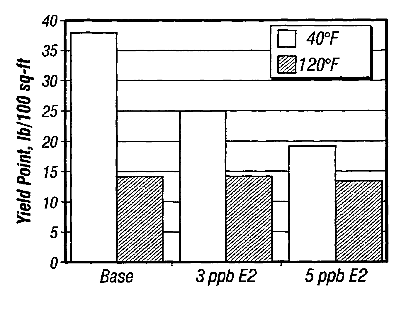
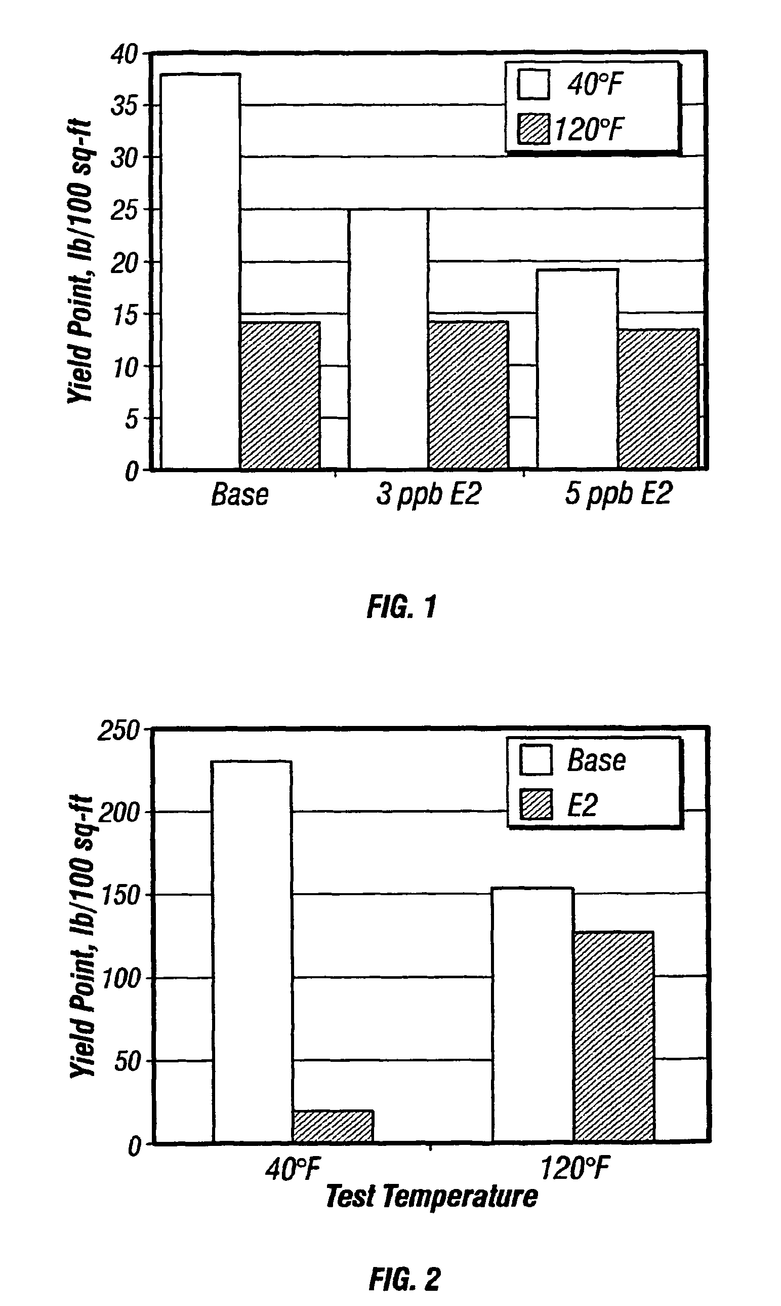
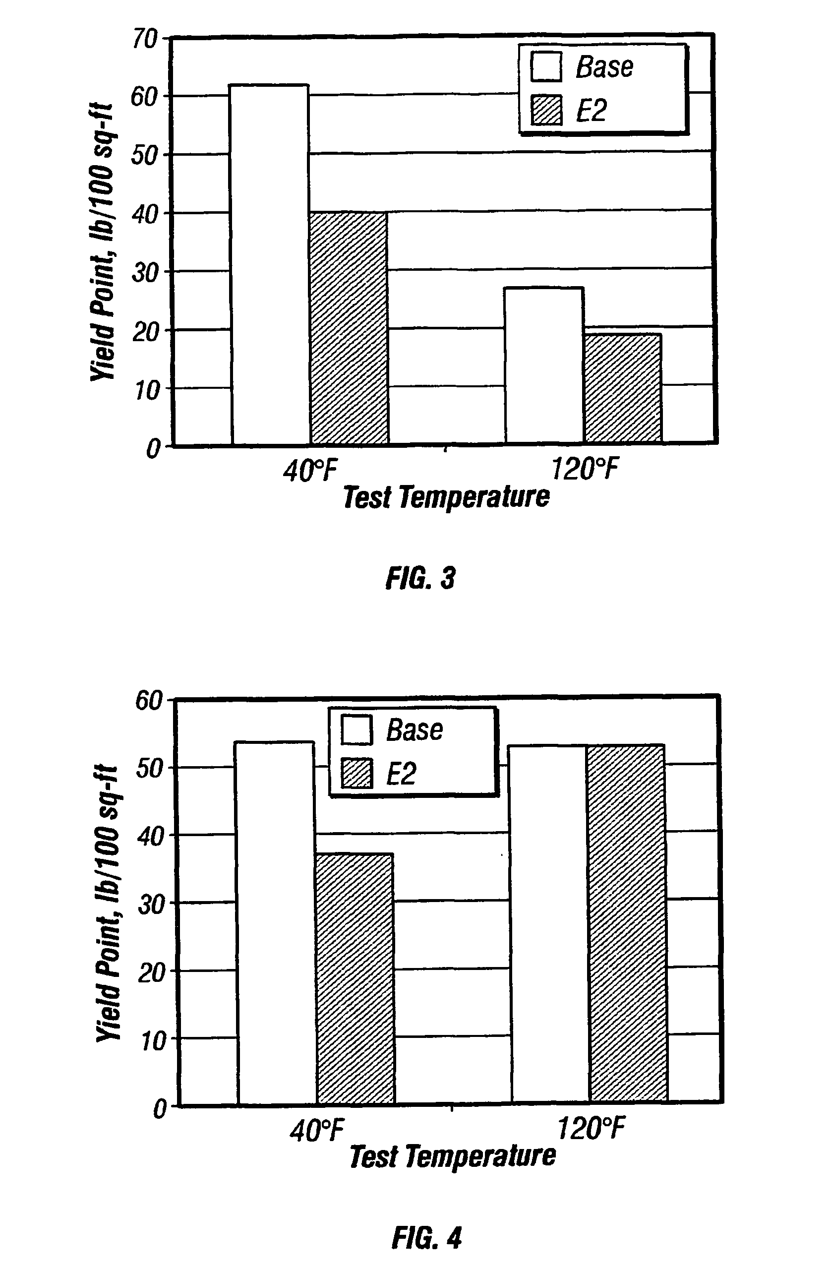
[0055]To show the effect of the invention, the following experiments were conducted. In each case an invert emulsion drilling mud system of the following general composition was prepared:

[0056]

Esterbbl0.496Waterbbl0.233Emulsifierlb6.0Organophilic bentonitelb1.0Organophilic lignitelb5.0Alkali reserve (lime)lb1.5CaCl2 × 2 H2Olb27.2Baritelb314.0Dispersing auxiliarylb0.5Thinnerlb / bbl2.0

[0057]The oil phase (A) used was a 2-ethylhexyl octanoate as disclosed in EP 0 386 636. The emulsifier used was the product EZ MUL NTE (Baroid Drilling Fluids Inc., Houston, Tex.). The oil / water ratio was 70 / 30 in each case. Measurements were carried out on a system without thinner (C1), and with a C12 / 14 fatty alcohol sulfate +2 EO, sodium salt (C2), with a C12 ether sulfate, sodium salt (C3) and with an oleic acid sulfonate disodium salt (C4), respectively, as prior art thinners, and comparison was made with these thinners and with compounds of formula (I) in accordance with the invention. The formula (...


PUM

PropertyMeasurementUnit
temperaturesaaaaaaaaaa

Abstract

A method of reducing the viscosity of oil-based drilling fluids and well service fluids at low temperatures and a thinner compound for use in such drilling fluids and well service fluids is disclosed. The method comprises adding to said drilling fluids or well service fluids a thinner having the formula:R—(C2H4O)n(C3H6O)m(C4H8O)k-Hwhere R is a saturated or unsaturated, linear or branched alkyl radical having about 8 to about 24 carbon atoms, n is a number ranging from about 1 to about 10, m is a number ranging form about 0 to about 10, and k is a number ranging from about 0 to about 10.

Description

BACKGROUND OF THE INVENTION[0001]1. Field of the Invention[0002]This invention is generally related to methods and compositions for drilling and servicing wellbores in hydrocarbon bearing subterranean formations. Particularly, this invention is related to oil-based drilling fluid systems comprising water-in-oil invert emulsions, and to thinners that enhance or enable use of such fluids, at temperatures at or below about 50 degrees Fahrenheit (about 10 degrees Centigrade).[0003]2. Description of Relevant Art[0004]A drilling fluid, or “mud” which a drilling fluid is also often called, is a specially designed fluid that is circulated in a wellbore as the wellbore is being drilled to facilitate the drilling operation. The various functions of a drilling fluid include removing drill cuttings from the wellbore, cooling and lubricating the drill bit, aiding in support of the drill pipe and drill bit, and providing a hydrostatic head to maintain the integrity of the wellbore walls and preve...

Claims


Application Information

Patent Timeline
Patent Type & Authority Patents(United States)
IPC IPC(8): C09K8/035C09K8/36C09K8/58C09K8/86E21B43/00E21B43/16
CPCC09K8/36
Inventor MUELLER, HEINZKIRSNER, JEFFBURROWS, KIMBERLY
Owner HALLIBURTON ENERGY SERVICES INC
Why Eureka
Try Eureka