Electrooptical device utilizing electrophoresis

Inactive Publication Date: 2008-10-14
E INK CORPORATION
View PDF23 Cites 0 Cited by
  • Summary
  • Abstract
  • Description
  • Claims
  • Application Information

AI Technical Summary

Benefits of technology

[0012]According to the first electrooptical device, using colored dispersion mediums of which colors (CMY) are complementary to the colors of electro-optic particles enables the apparatus to have high intensity of color and high contrast, with both of the color density and a cell thickness kept to their minimums. Further, since the cell can be formed into a thinner one, the intensity of an electric field required for electrophoresis can be realized by lower applied voltage than the conventional voltage. Hence the voltage to drive the cell can be lowered markedly. Further, the thinner cell makes it possible to switch the cell ON / OFF at higher speed, which leads to display of dynamic images identical or superior to or than that performed with liquid crystal display.
[0017]According to the second electrooptical device, using the black-colored dispersion medium enables the apparatus to have high intensity of color and high contrast, with both of the color density and a cell thickness kept to their minimums. Further, since the cell can be formed into a thinner one, the intensity of an electric field required for electrophoresis can be realized by lower applied voltage than the conventional voltage. Hence the voltage to drive the cell can be lowered markedly. Further, the thinner cell makes it possible to switch the cell ON / OFF at higher speed, which leads to display of dynamic images identical or superior to or than that performed with liquid crystal display. Coloring of the dispersion medium can be done in common regardless of the colors of the particles, which is advantageous in production cost.
[0022]According to the third electrooptical device, using a colored dispersion medium that absorbs a color of electrophoretic particles enables the apparatus to have high intensity of color and high contrast, with both of the color density and a cell thickness kept to their minimums. Further, since the cell can be formed into a thinner one, the intensity of an electric field required for electrophoresis can be realized by lower applied voltage than the conventional voltage. Hence the voltage to drive the cell can be lowered markedly. Further, the thinner cell makes it possible to switch the cell ON / OFF at higher speed, which leads to display of dynamic images identical or superior to or than that performed with liquid crystal display. Limitations on coloring the dispersion medium are reduced as well, with the result that choice in materials of the dispersion medium is widened. Hence this makes it possible to improve characteristics of display.
[0025]According to the fourth electrooptical device, high intensity of color and high contrast can be obtained, with both of the color density and a cell thickness kept to their minimums. Further, voltage to drive the cell can be lowered markedly. Still, a thinner cell makes it possible to switch the cell ON / OFF at higher speed, which leads to full-color display of dynamic images identical or superior to or than that performed with liquid crystal display. Arbitrary two colors can be selected to combine with each other, thereby providing multi-color display. The fourth electrooptical device can be used in any applications as the next-generation display that exceeds CRTs and liquid crystal displays.
[0028]According to the fifth electrooptical device, high intensity of color and high contrast can be obtained, with both of the color density and a cell thickness kept to their minimums. Further, voltage to drive the cell can be lowered markedly. Still, a thinner cell makes it possible to switch the cell ON / OFF at higher speed, which leads to full-color display of dynamic images identical or superior to or than that performed with liquid crystal display. Arbitrary two colors can be selected to combine with each other, thereby providing multi-color display. Coating microcapsules onto a flexible substrate is able to provide displays such as sheets of paper that exceed CRTs and liquid crystal displays.

Problems solved by technology

However, practical materials of dispersion which permits given modulation required to produce color images have not been considered up to now.

Method used


Image

  • Electrooptical device utilizing electrophoresis
  • Electrooptical device utilizing electrophoresis
  • Electrooptical device utilizing electrophoresis

Examples


first embodiment

A. First Embodiment

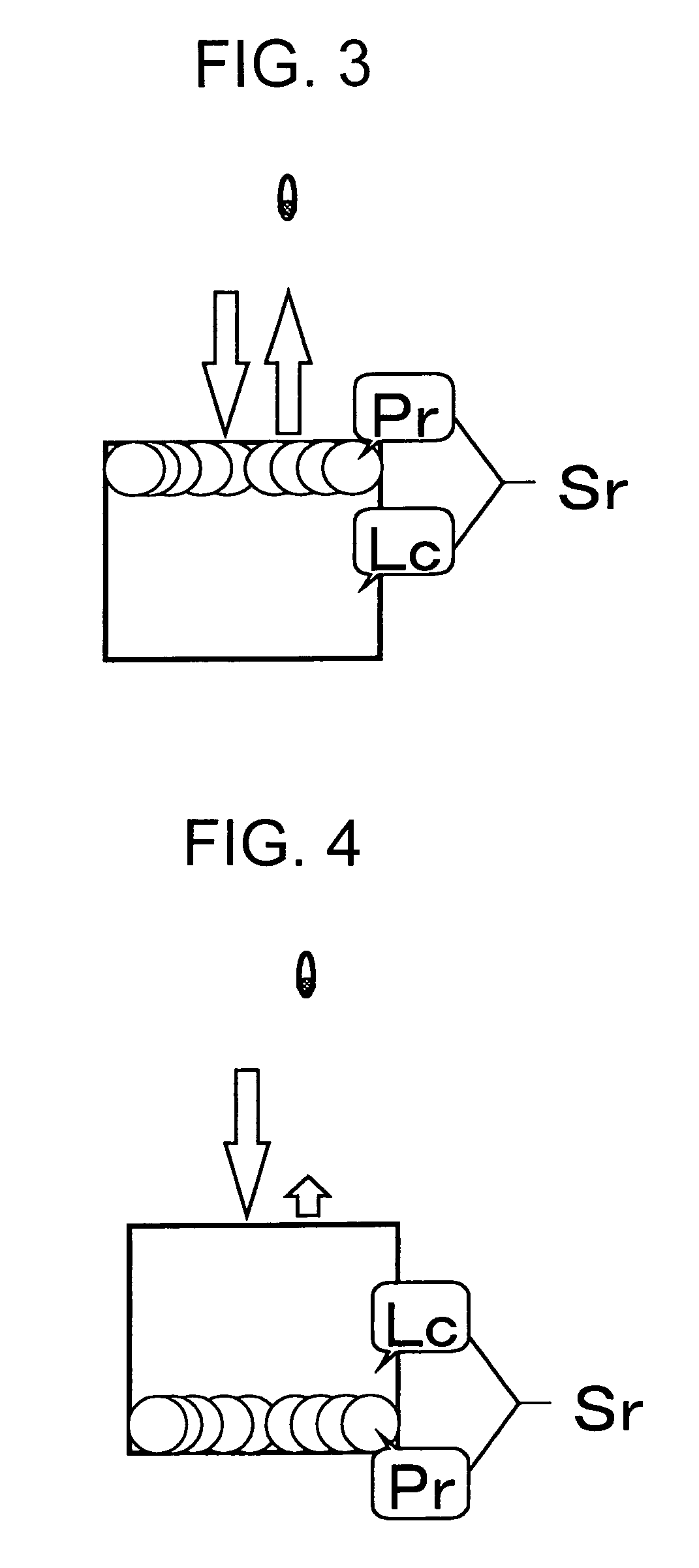
[0072]FIGS. 3 and 4 show sectional views of a cell for display of red (R). Although one display panel is composed of a plurality of such cells, constituents such as electrodes and a bulkhead are omitted from being depicted for the sake of simplified explanation. Electrophoretic particles Pr have a characteristic of reflecting the component of red (R). A dispersion medium (Lc) is colored cyan (C) to absorb the wavelength component of the red (R). When applied voltage causes the electrophoretic particles Pr to migrate to an electrode located to the user side, a state shown in FIG. 3 is realized. In this case, the electrophoretic particles Pr can be seen directly by the user, where the red is displayed brightly. On the other hand, when the electrophoretic particles migrate to the electrode opposite to the user, a state shown in FIG. 4 is provided. In this situation, incidence light is subject to absorption of the colored dispersion medium (Lc), reflected by the elect...

second embodiment

B. Second Embodiment

[0076]FIGS. 9 and 10 show sectional views of a cell for display of red (R). For the sake of simplified explanation, constituents such as electrodes and a bulkhead are omitted from being depicted. Electrophoretic particles Pr have a characteristic of reflecting the component of red (R). A dispersion medium (Lk) is colored black. When applied voltage causes the electrophoretic particles Pr to migrate to an electrode located at the user side, a state shown in FIG. 9 is realized. In this case, the electrophoretic particles Pr can be seen directly by the user, where a bright red is displayed. On the other hand, when the electrophoretic particles migrate to the electrode opposite to the user, a state shown in FIG. 10 is provided. In this case, the cell is displayed in a dark red or black, because the incidence light experiences the absorption of the colored dispersion medium (Lk). Although the cell is depicted to have a rectangular section, its shape is not limited to ...

third embodiment

C. Third Embodiment

[0080]FIGS. 15 and 16 show sectional views of a cell for display of red (R). For the sake of simplified explanation, constituents such as electrodes and a bulkhead are omitted from being depicted. Electrophoretic particles Pr have a characteristic of reflecting the component of red (R). A dispersion medium (Lkr) is colored so as to absorb at least a wavelength component of the red (R). When applied voltage causes the electrophoretic particles Pr to migrate to an electrode located at the user side, a state shown in FIG. 15 is realized. In this case, the electrophoretic particles Pr can be seen directly by the user, where a bright red is displayed. On the other hand, when the electrophoretic particles migrate to the electrode opposite to the user, a state shown in FIG. 16 is provided. In this case, the cell is displayed in a dark red or black, because the incidence light experiences the absorption of the colored dispersion medium (Lkr). Although the cell is depicted...


PUM

PropertyMeasurementUnit
Coloraaaaaaaaaa
Wavelengthaaaaaaaaaa
Electrooptical effectaaaaaaaaaa

Abstract

An electrooptical device comprises an electrooptical layer between electrodes. The electrooptical layer includes a dispersion medium and particles contained in the dispersion medium. The particles are colored a first color, while the dispersion medium is colored a second color. The first and second colors are related to each other based on a relationship of complementary colors.

Description

[0001]This is a Continuation-in-Part of application Ser. No. 09 / 822,420 filed Apr. 2, 2001 now abandoned. The entire disclosure of the prior application is hereby incorporated by reference herein in its entirety.BACKGROUND OF THE INVENTION[0002]1. Field of Technical Art[0003]The present invention relates to electrooptical devices utilizing electrophoresis and, in particular, to electrooptical devices and electronic apparatuses capable of performing full color display with superior color reproducibility.[0004]2. Description of Related Art[0005]Japanese Patent publication No. 49-32038 discloses a structure that consists of a pair of sheets, a porous spacer having a large number of pores and inserted between the sheets, and dispersion filled in each pore so as to be divided into minute areas. This publication explains that each divided area of dispersion provides a cell modulated in red, green or blue and these cells are able to perform color display on the basis of the additive color ...

Claims


Application Information

Patent Timeline
IPC IPC(8): G02F1/01G02B26/00G02F1/13G02F1/167
CPCG02F1/167Y10T428/10G02F2203/34Y10T428/249995C09K2323/00
Inventor KATASE, MAKOTO
Owner E INK CORPORATION
Why Eureka
Try Eureka