Head mountable video display

a display and head technology, applied in the field of direct retinal image projection, can solve the problems of eye strain, disorientation and confusion, and achieve the effect of high quality and convenient modulation of each rgb beam

Inactive Publication Date: 2008-10-14
KUYKENDALL JR JACOB L
View PDF2 Cites 152 Cited by
  • Summary
  • Abstract
  • Description
  • Claims
  • Application Information

AI Technical Summary

Benefits of technology

[0013]The un-modulated light beams from the LED sources are polarized and divided into two beams through a polarized/beam splitter optical element which is fabricated using a single truncated cube, to direct the two beams to dual multi-wave guide optical cables that carry the images to each of the retinas through the eyeglasses integrated direct retinal projection s

Problems solved by technology

Conversely, if stereo 3-D is delivered by way of a CRT of LCD screen, the user becomes stressed as the result of having two possible points of focus, the face of

Method used


Image

  • Head mountable video display
  • Head mountable video display
  • Head mountable video display

Examples


Embodiment Construction

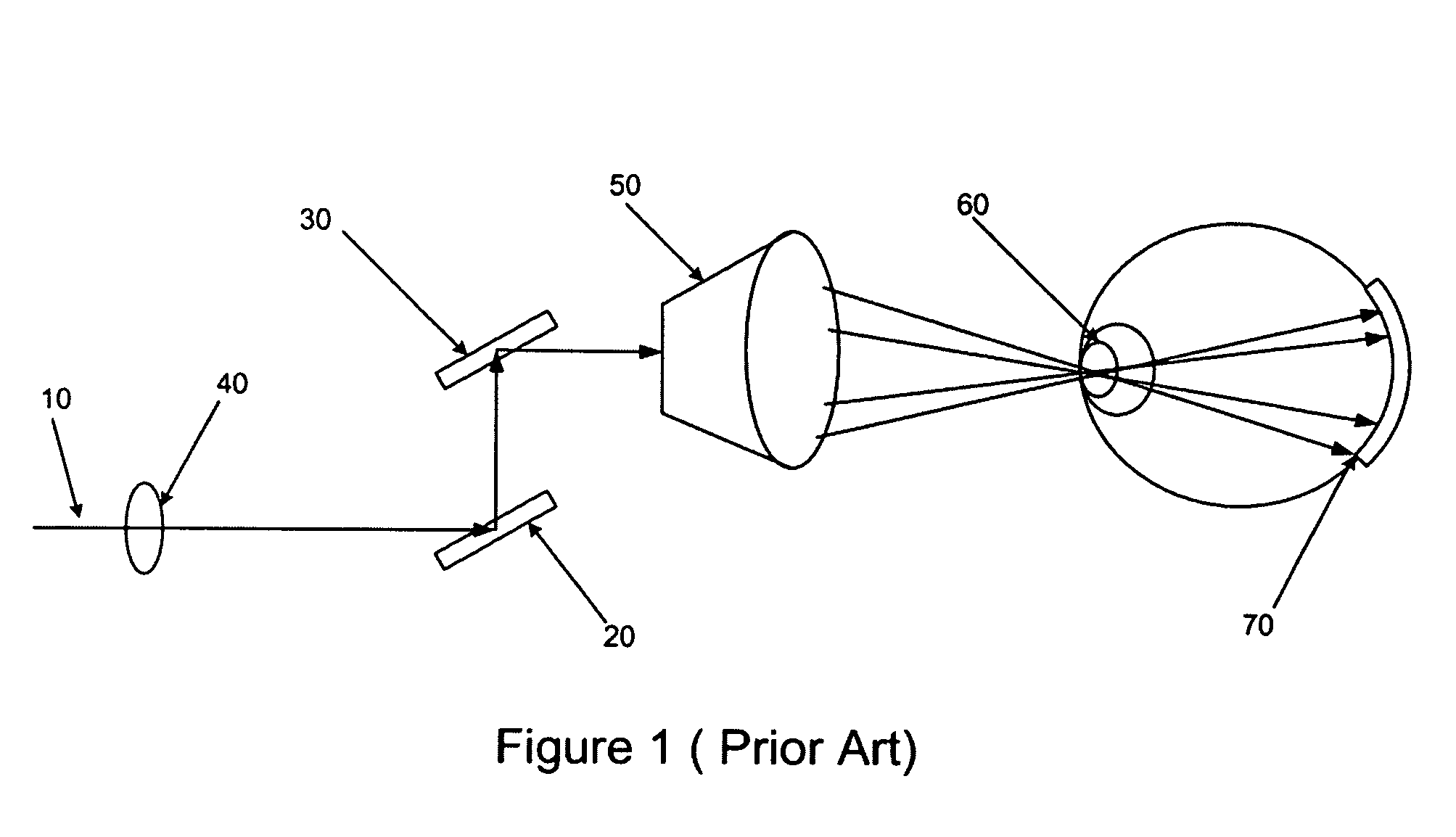
[0023]Referring to FIG. 1, a pictorial and block diagram is shown of a typical, prior art system that utilized a modulated low-power photon source 1 that is controllable both horizontally 3 and vertically 4. The modulated photon source is focused through an achromatic focusing lens 2 before it reaches the horizontal scanning mirror 3. With this approach, the process that controls the signal that paints the images onto the retina 7 is similar to that of a classic TV CRT, but the process uses photons and not electrons. The light beam's final pass bounces off a small reflecting surface 5 before entering the lens of the eye 6 and imaging onto the retina 7. To obtain color with this approach, three separate lasers are used, each with the desired red, green, blue wavelengths. Variations to this legacy approach are to utilize a miniature, low resolution CRT or liquid crystal display panel that is mounted in front of one or both of the eyes. As the size of the display with this methodology ...


PUM


Abstract

The invention comprises a distributed direct retinal display projection system that can be fabricated as an embedded, integral part of an eyeglasses frame and can be configured to address a wide range of commercial, consumer and military applications. A system is described comprising a video processing module that may worn on a belt or carried in a pocket, which transmits an image through a multi-waveform optical cable that is configured with a wave guide per pixel.

Description

[0001]This application claims the benefit of priority from previously filed U.S. Provisional Patent Applications Nos. 60 / 602,002, filed Aug. 17, 2004, 60 / 606,717, filed Sep. 2, 2004, 60 / 619,472 filed Oct. 18, 2004 60 / 642,578 filed Jan. 11, 2005, each of which is incorporated herein by reference.FIELD OF INVENTION[0002]The invention relates generally to direct retinal image projection, and more particularly to 3-D head mounted display systems.BACKGROUND OF THE INVENTION[0003]Direct retinal projection systems have been in existence over the past decade and have been applied primarily to niche applications. There has not been wide application or demand at the consumer level, however, due to low resolution, high cost and the inability of current designs to be shrunk to a size that can be conveniently and comfortably worn by a user.[0004]In the military environment, it was recognized that in today's high speed and complex aircraft that it was dangerous for a pilot to have to look down at...

Claims


Application Information

Patent Timeline
IPC IPC(8): G02F1/03
CPCG02B27/0172G02B5/30G02B6/00G02B2027/0134
Inventor KUYKENDALL, JR., JACOB L.
Owner KUYKENDALL JR JACOB L
Why Eureka
Try Eureka