Self-contained apparatus for inspection of electric conductors

a self-contained, conductor technology, applied in the direction of instruments, specific gravity measurement, line-transmission details, etc., can solve the problems of inability to test the area under the unit, the effect of looking at the effects of corrosion, and only detecting damage to the outer strand of the conductor

Active Publication Date: 2008-10-21
UNIVERSITY OF DENVER
View PDF3 Cites 12 Cited by
  • Summary
  • Abstract
  • Description
  • Claims
  • Application Information

AI Technical Summary

Benefits of technology

[0009]Therefore it is an object of the invention to provide a self-contained apparatus that can detect small flaws in a conductor quickly and efficiently, whether the conductor is energized or de-energized.

Problems solved by technology

Further, line personnel are only able to detect damage to the outer strands of the conductor and cannot see critical sub-surface damage.
While this technology is able to detect corrosion in the conductor core, it does not look at the effects of corrosion on the outer conductor strands.
Also, the unit is not capable of testing areas under suspension clamps unless they are removed, thus, requiring the conductor to be de-energized.
Further, OHLCD technology does not detect strand breaks or non-functional splice repairs.
However, these techniques have been less successful at the detection of flaws in overhead transmission conductors.
Infrared or X-ray surveys of transmission conductors require an airplane and other expensive equipment.
The costs of such services and the limited results they yield have yet to demonstrate a real cost-benefit justification.
The high-cost and time-intensive nature of the methods described above coupled with tight operational and maintenance budgets have resulted in infrequent conductor inspection and a growing risk of failure that is neither quantified nor fully understood.
As a result, companies are forced to make decisions regarding the replacement of power transmission conductors without proper diagnosis tools.
These decisions often result in the replacement of conductors with remaining life and the non-replacement of conductors near failure, thereby resulting in substantial costs per year for unneeded replacements.

Method used


Image

  • Self-contained apparatus for inspection of electric conductors
  • Self-contained apparatus for inspection of electric conductors
  • Self-contained apparatus for inspection of electric conductors

Examples


Embodiment Construction

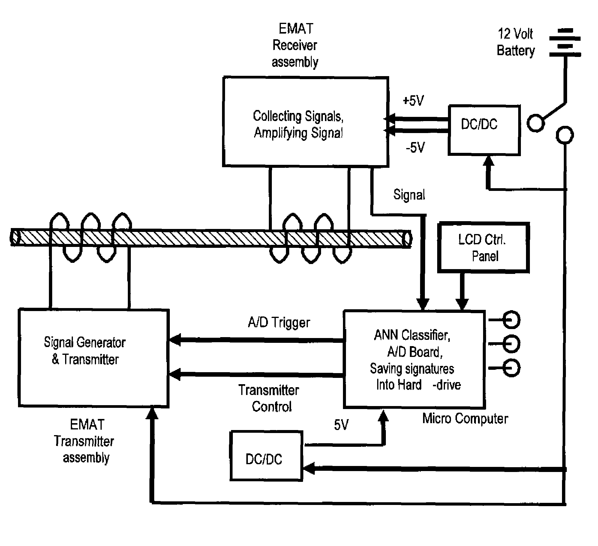
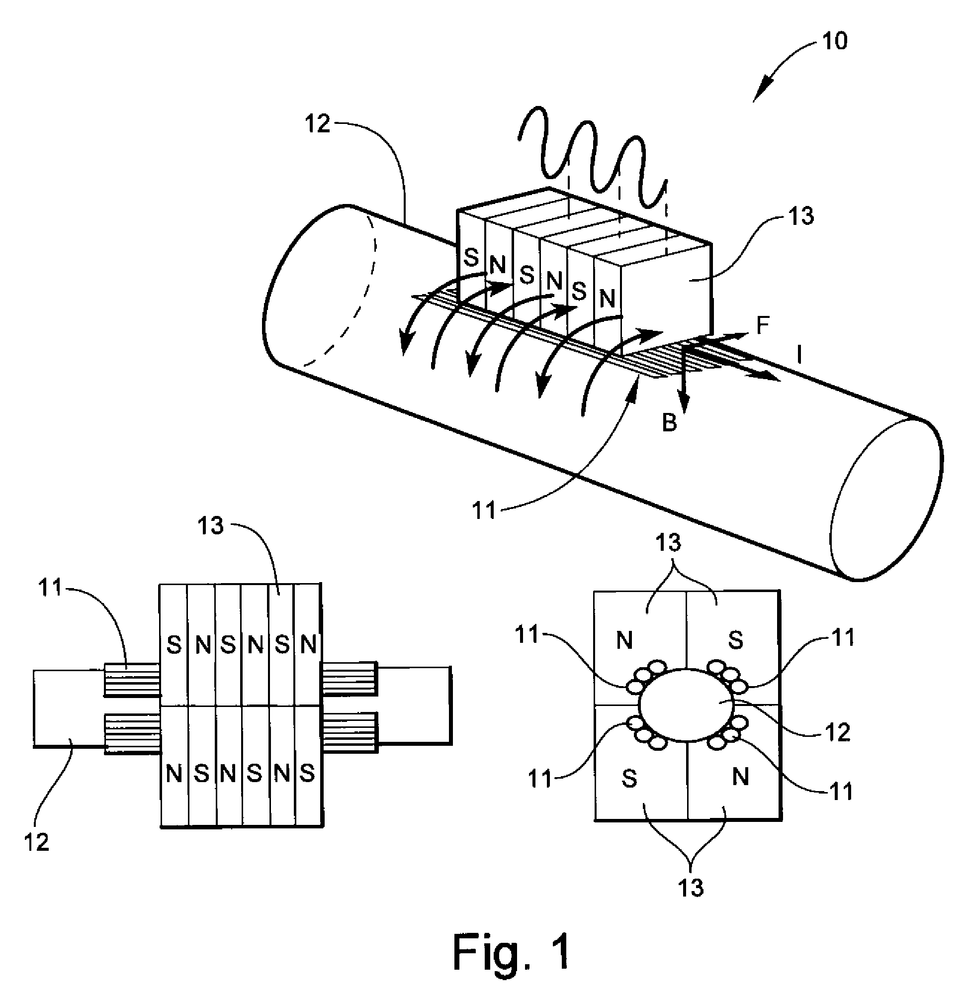
[0071]Referring to FIG. 1, the present invention utilizes Electromagnetic Acoustic Transducers (EMAT) to monitor, diagnose, and identify failures in an energized or de-energized conductor, i.e. transmission lines. An EMAT 10 consists of a transmitter and a receiver. The EMAT 10 couples ultrasonic energy into conductive materials. The simplest form of an EMAT 10 is a wire loop held near a conductive material with a magnet placed above the wire. The transmitter operates based on principles similar to an electric motor, which develops torsional waves. As shown, a copper coil 11 is placed as close to a test specimen 12 as possible and an alternating current is injected. This current produces a dynamic magnetic field (H), which varies in time and space. The resulting eddy current density (J) produced in the test specimen 12 is given by Maxwell's equation, represented by:

{right arrow over (J)}={right arrow over (∇)}×{right arrow over (H)}  (1)

From Maxwell's equations for quasi-static cond...


PUM

PropertyMeasurementUnit
currentaaaaaaaaaa
voltage levelaaaaaaaaaa
voltageaaaaaaaaaa

Abstract

A self-contained apparatus for inspecting energized and de-energized conductors. The apparatus includes a housing, at least one transmitter contained within the housing for generating and impinging pulses onto an electrical conductor, such that the pulses travel through and are reflected by the electrical conductor, and at least one receiver contained within the housing for receiving reflected pulses from the electrical conductor. The apparatus further including a controller for determining a condition of the electrical conductor based on an evaluation of the reflected pulses, and at least one indicator for displaying the condition of the electrical conductor determined by the controller.

Description

TECHNICAL FIELD AND BACKGROUND OF THE INVENTION[0001]The present invention relates to the field of electric conductor inspection. In particular, the invention relates to a self-contained apparatus for inspecting energized and de-energized conductors.[0002]Utility companies have long sought to reap the benefits of early detection of overhead power line / conductor defects. Identifying conductor issues early can facilitate the maintenance and replacement decision making process and prioritize repairs that should be made. Correctly separating troubled conductors from those with additional life can help companies avoid expensive maintenance work, line-drops, failures, and regional outages.[0003]A number of methods and technologies have been used to detect damaged or aged transmission conductors. These include visual inspection, infrared thermography, and overhead line corrosion detection (OHLCD).[0004]The traditional method for detecting damage to an overhead transmission conductor has re...

Claims


Application Information

Patent Timeline
Patent Type & Authority Patents(United States)
IPC IPC(8): G01N29/04G01R31/11
CPCG01N29/223G01N29/2412G01N29/4481G01N2291/044G01N2291/102G01N2291/2698G01R15/142
Inventor SHOURESHI, RAHMAT A.
Owner UNIVERSITY OF DENVER
Why Eureka
Try Eureka