
Dual source XRF system

a technology of xrf and xrf, applied in the field of xray fluorescence (xrf) techniques and systems, can solve the problems of reducing the signal-to-background ratio of other elements, making the analysis of low levels (80 ppm) of aluminum and silicon extremely difficult if not impossible, and not being able to use the same tube anode material. , to achieve the effect of convenient us

Active Publication Date: 2008-10-21
OLYMPUS SCI SOLUTIONS AMERICAS
View PDF6 Cites 9 Cited by
  • Summary
  • Abstract
  • Description
  • Claims
  • Application Information

AI Technical Summary

Benefits of technology

[0014]It is a further object of this invention to provide such an XRF system which is more robust, easy to use, and ergonomic in design.
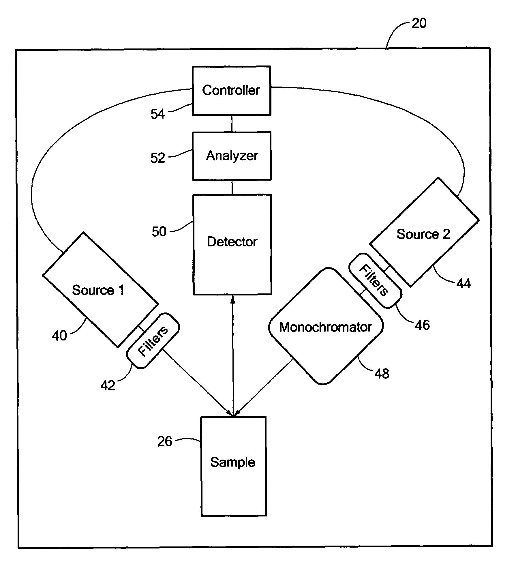
[0015]The subject invention results from the realization that by incorporating at least two x-ray sources in an XRF system, the concentration of different elements in a sample can be more reliably determined and, moreover, the concentration of one element based on irradiation of the sample by one x-ray source can be taken into account when determining the concentration of another element after irradiation of the sample by the other x-ray source. A dual tube system is effected whereby a sample is automatically measured sequentially by the first source, then the second source, and the results from the first source measurement are used to automatically correct the results from the second source. Moreover, one or both sources are tuned so that they optimally excite one group of elements but minimally excite the other group of elements. Since high concentrations of one or more elements in the sample may interfere with the measurements of other elements in the sample, the subject invention overcomes certain limitations associated with the prior art. In one embodiment, either or both sources may be used in combination with a monochromator to produce a quasi mono-energetic x-ray source.

Problems solved by technology

A general problem in XRF analysis is the need to analyze a wide range of elements in a sample whereby high concentrations of some elements mask the presence of, or interfere with, low concentrations of other elements that also must be measured.
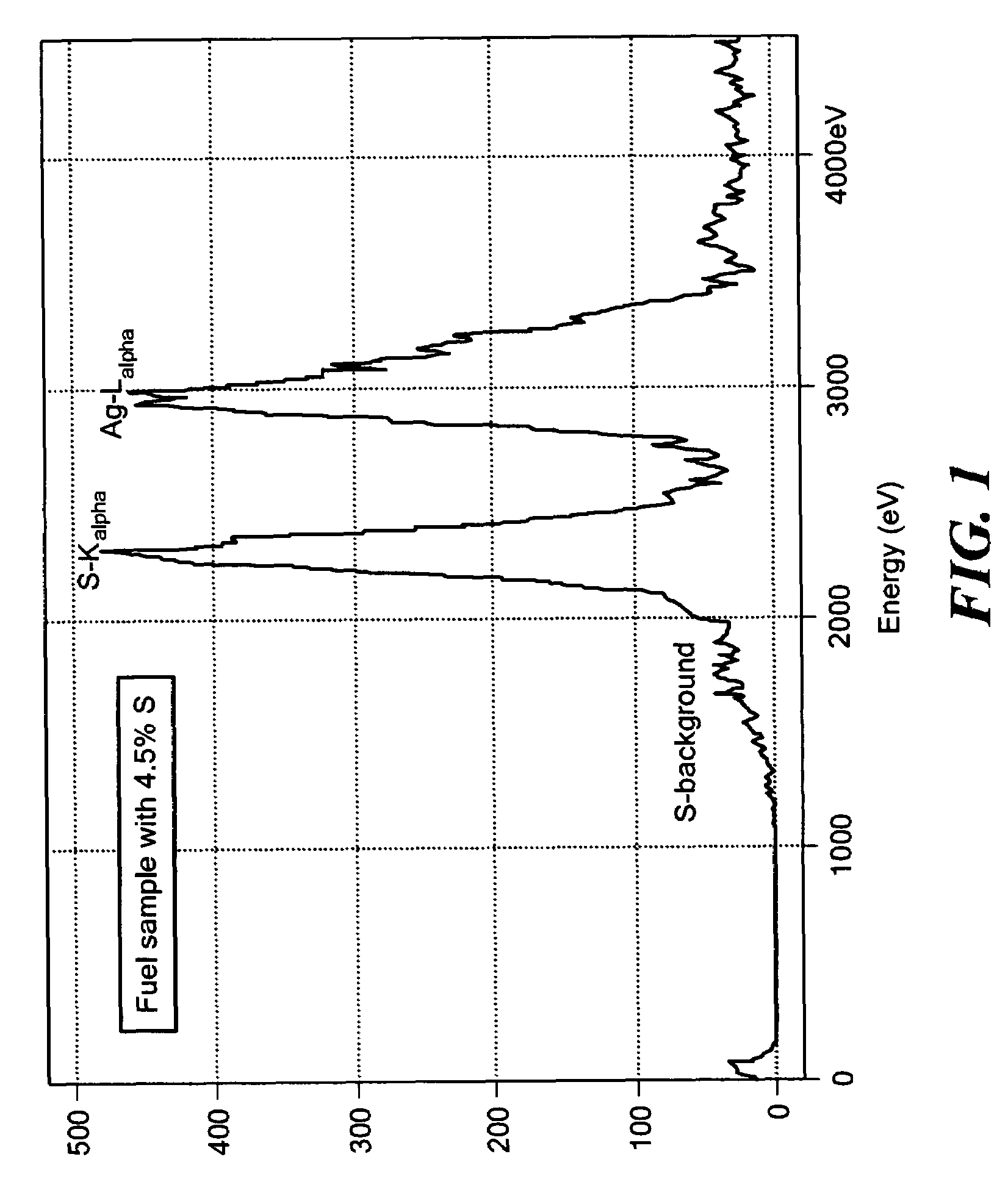
The large peak in the spectrum generates excessive background in the detector that reduces the signal-to-background ratio of other elements.
In an XRF system with a single x-ray tube, the spectrum would be dominated by the high levels (0.5-5.0%) of sulfur in the sample which makes the analysis of low levels (<80 ppm) of aluminum and silicon extremely difficult if not impossible.
However, for the situation where one of the elements to be measured by a direct beam is sulfur, and the elements to be measured by the monochromatic beam are aluminum and silicon, it is not possible to use the same tube anode material.
This is because the Mo-L line (2.29 keV) lies at almost the same energy as S (2.307 keV), which means that it would not be possible to quantify the amount of sulfur in a sample.
But, a fuel sample would typically be analyzed in the field often by less knowledgeable technicians.

Method used


Image

  • Dual source XRF system
  • Dual source XRF system
  • Dual source XRF system

Examples


Embodiment Construction

[0028]Aside from the preferred embodiment or embodiments disclosed below, this invention is capable of other embodiments and of being practiced or being carried out in various ways. Thus, it is to be understood that the invention is not limited in its application to the details of construction and the arrangements of components set forth in the following description or illustrated in the drawings. If only one embodiment is described herein, the claims hereof are not to be limited to that embodiment. Moreover, the claims hereof are not to be read restrictively unless there is clear and convincing evidence manifesting a certain exclusion, restriction, or disclaimer.

[0029]FIG. 1 shows a spectrum from a standard XRF measurement. A high sulfur peak is seen in the region around the x-axis value of 2,300 eV. The area of interest for aluminum and silicon is approximately 1,500 and 1,750 eV respectively. The background “tailing” from the high sulfur concentration extends down to past the low...


PUM

PropertyMeasurementUnit
atomic numberaaaaaaaaaa
dual source XRFaaaaaaaaaa
concentrationaaaaaaaaaa

Abstract

A dual source tube XRF system and method wherein a first x-ray source is employed to direct x-rays in a first energy band at a sample and at least a second x-ray source is employed to direct x-rays in a second energy band at the sample. A detector is responsive to x-rays emitted by the sample after irradiation by the first and second x-ray sources. An analyzer is responsive to the detector and is configured to determine the amount of at least a first substance in the sample based on irradiation of the sample by the first x-ray source and to determine the amount of at least a second substance in the sample based on irradiation of the sample by the second x-ray source. A controller is responsive to the analyzer and is configured to energize the first and second x-ray sources either simultaneously or sequentially.

Description

FIELD OF THE INVENTION[0001]This subject invention relates to x-ray fluorescence (XRF) techniques and systems and, in one particular example, to an XRF system and method used to analyze fuels, oils, and additives.BACKGROUND OF THE INVENTION[0002]X-ray fluorescence (XRF) is a technique used to measure the elemental composition of a sample. The sample is excited by a source of x-rays, and emits its own characteristic x-rays. A detector is responsive to the x-rays emitted from the sample. An analyzer processes the output signals produced by the detector and divides the energy levels of the detected x-ray photons into energy subranges by counts of the number of x-ray photons detected to produce a graph depicting the x-ray spectrum of the sample.[0003]In XRF, the sample is irradiated with x-rays either from a radioactive isotope source or, more commonly, from an x-ray tube. A typical isotope source, for example Fe-55, has a limited range of emitted x-ray energies which cannot be changed....

Claims


Application Information

Patent Timeline
Patent Type & Authority Patents(United States)
IPC IPC(8): G01N23/223
CPCG01N33/287G01N23/223G01N2223/076
Inventor HUBBARD-NELSON, BRADLEYHARDMAN, PETER JOHN
Owner OLYMPUS SCI SOLUTIONS AMERICAS
Learn More