Control device for internal combustion engine

a control device and internal combustion engine technology, applied in the direction of electric control, combustion engine, charge feed system, etc., can solve the problems of not taking into account volumetric efficiency, temporary drop in rotational speed of the engine, and not taking into account methods, etc., to achieve short calculation time, reduce the number of man-hours, and high accuracy

Active Publication Date: 2008-10-28
MITSUBISHI ELECTRIC CORP
View PDF13 Cites 42 Cited by
  • Summary
  • Abstract
  • Description
  • Claims
  • Application Information

AI Technical Summary

Benefits of technology

[0016]The present invention has been made to solve the above-mentioned problems, and it is therefore an object of the present invention to provide a control device for an internal combustion engine capable of calculating with high accuracy a target engine intake air flow quantity in the vicinity of a throttle valve with a reduced number of man-hours and in a shorter calculation time such that an actual cylinder intake air flow quantity swiftly converges at a target cylinder intake air flow quantity even during transitional operation, and controlling a throttle opening degree in accordance with the target engine intake air flow quantity.
[0019]It is therefore possible to calculate the actual cylinder intake air flow quantity with high accuracy, using simple operational expressions derived from a physical model for the intake system.
[0021]It is therefore possible to calculate with high accuracy the target engine intake air flow quantity in the vicinity of the throttle valve with a reduced number of man-hours and in a shorter calculation time such that the actual cylinder intake air flow quantity swiftly converges at the target cylinder intake air flow quantity even during transitional operation, using the simple operational expressions derived from the physical model for the intake system, and to control the throttle opening degree in accordance with the target engine intake air flow quantity.

Problems solved by technology

However, the conventional device disclosed in JP 05-38143 A does not take into account a volumetric efficiency equivalent value of air sucked into cylinders from an intake pipe, which includes the influences of intake valves and exhaust valves of the engine.
Therefore, in an engine having, for example, a mechanism for variably controlling intake valves and exhaust valves, there is a problem in that a great error occurs between a flow quantity of intake air actually sucked into the cylinders and an air amount calculated by the AN calculation unit in a certain operation range during transitional operation.
However, the conventional device disclosed in JP 2005-54657 A does not take into account a method of controlling response characteristics during transitional operation.
Thus, there is a problem in that the rotational speed of the engine temporarily drops due to an increased discrepancy between a target engine intake air flow quantity corresponding to a target torque of the engine and the detected value of the amount of fresh air passing through the intake passage (actual engine intake air flow quantity).
Therefore, there is a problem in that an increase in the number of man-hours for matching, an increase in the number of man-hours for check and assessment, and an extension of calculation time are caused.

Method used


Image

  • Control device for internal combustion engine
  • Control device for internal combustion engine
  • Control device for internal combustion engine

Examples


first embodiment

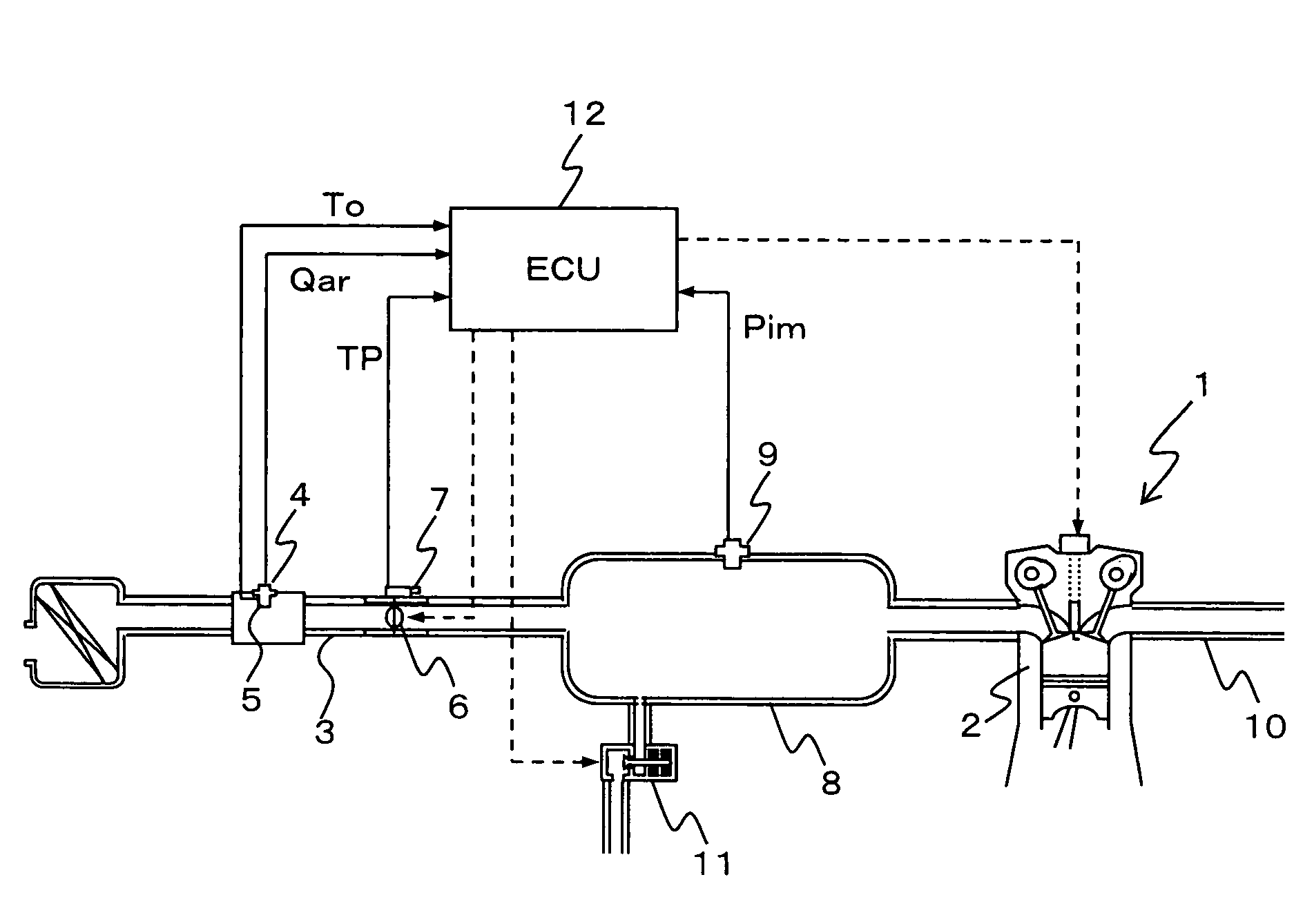
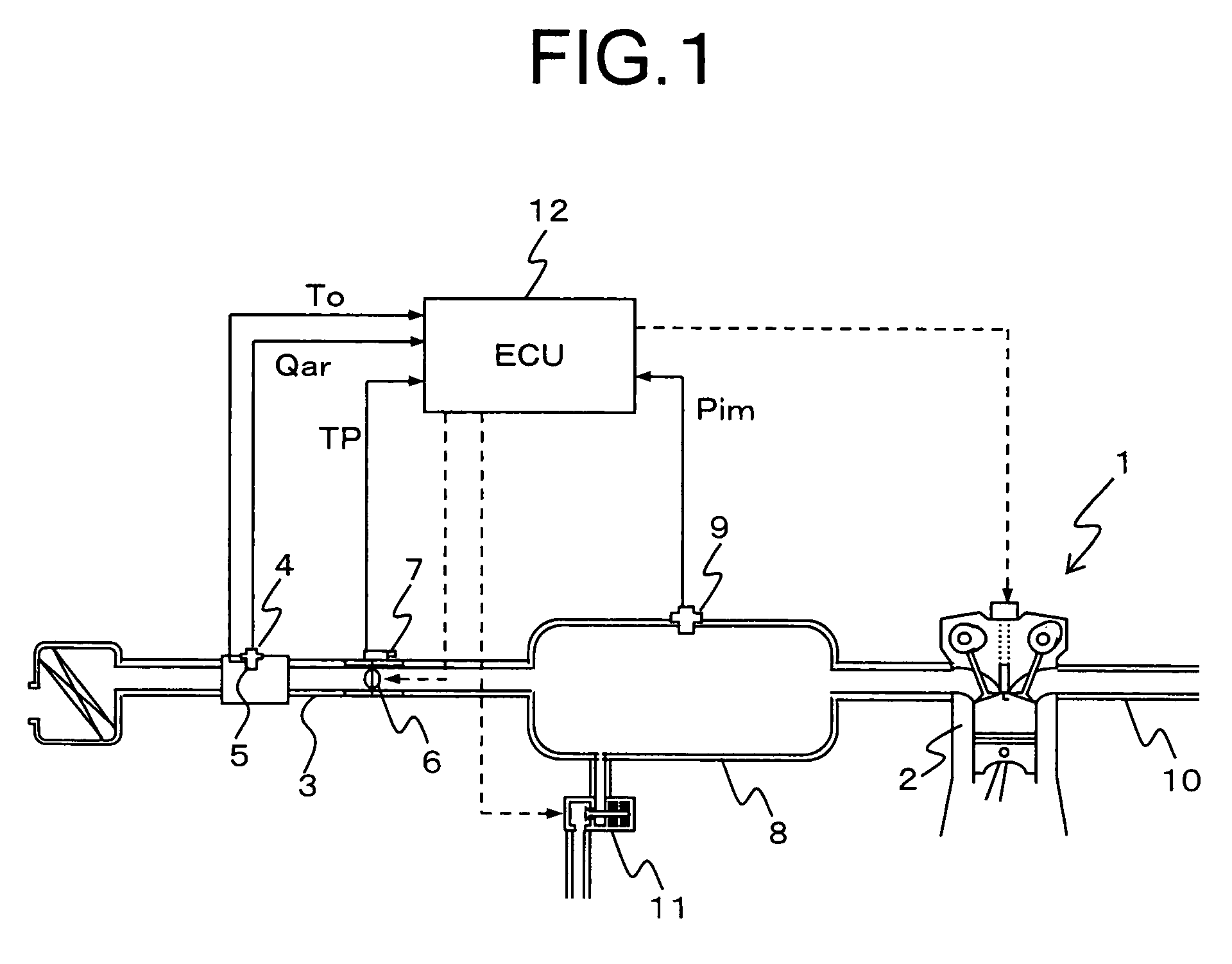
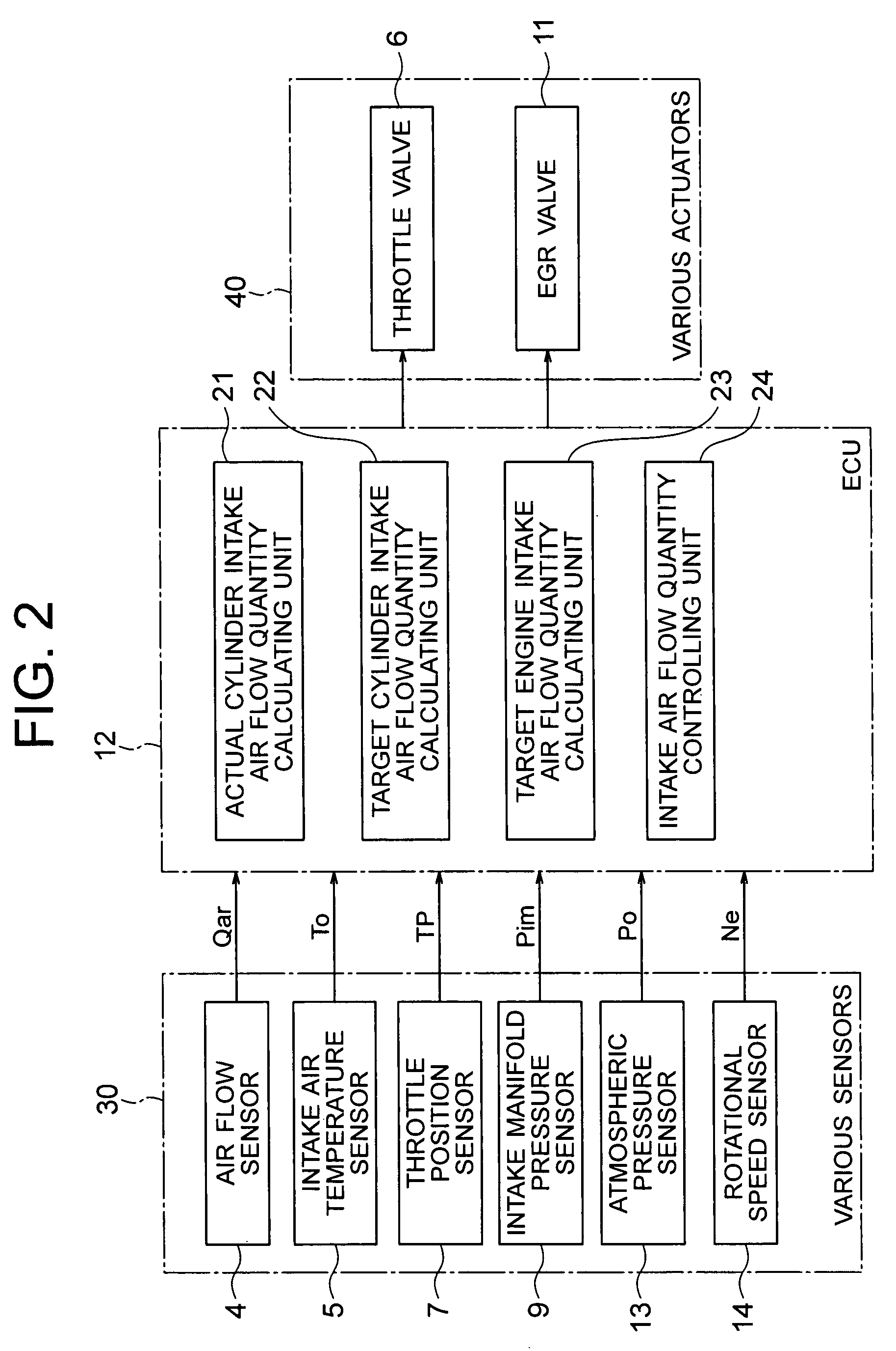
[0035]FIG. 1 is a schematic diagram roughly showing a control device for an internal combustion engine according to the first embodiment of the present invention. FIG. 2 is a block diagram roughly showing a construction of an engine control portion of the control device for the internal combustion engine according to the first embodiment of the present invention.

[0036]Although the internal combustion engine is generally provided with a plurality of cylinders 2, one of the cylinders 2 will be described in the following embodiments of the present invention.

[0037]Referring to FIG. 1, provided upstream of an intake pipe 3 constituting an intake system of an engine 1 (internal combustion engine) are an air flow sensor 4 (intake air flow quantity detecting unit) for measuring a flow quantity Qar of air actually sucked by the engine 1 (hereinafter abbreviated as “the actual engine intake air amount Qar”) and an intake air temperature sensor 5 for measuring a temperature To of intake air (h...

second embodiment

[0124]FIG. 9 is a block diagram roughly showing the construction of an engine control portion of a control device for an internal combustion engine according to the second embodiment of the present invention.

[0125]Referring to FIG. 9, an ECU 12A further includes a variable valve mechanism control unit 27 for variably controlling an actuation state of at least either intake valves (not shown) or exhaust valves (not shown) of the engine 1. The ECU 12A includes an actual cylinder intake air flow quantity calculating unit 21A instead of the actual cylinder intake air flow quantity calculating unit 21 shown in FIG. 2.

[0126]It should be noted herein that a relationship between the rotational speed Ne and the intake manifold pressure Pim on the one hand and the volumetric efficiency correction coefficient Kv on the other is measured in the engine 1 in advance for each of actuation states such as lift and phase angle of the intake valves or the exhaust valves, and stored in the memory as a ...

third embodiment

[0139]In a case where an actual engine control system is taken into account, although not mentioned in the foregoing first embodiment of the present invention, a predetermined dead time and a predetermined response delay may occur until the actual engine intake air amount Qar measured by the air flow sensor 4 is input to the ECU 12 after the target engine intake air flow quantity calculating unit 23 calculates the target engine intake air amount Qat.

[0140]In this case, the following respective procedures are carried out until the actual engine intake air amount Qar is input after the target engine intake air amount Qat is calculated. That is, the intake air flow quantity controlling unit 24 controls the throttle opening degree TP based on the target engine intake air amount Qat, air in the vicinity of the throttle valve 6 responds thereto to exert an influence on air in the vicinity of the air flow sensor 4, and the air flow sensor 4 measures the actual engine intake air amount Qar....


PUM


Abstract

Provided is a control device for an internal combustion engine, which is provided to allow a throttle opening degree to be controlled in accordance with a target engine intake air flow quantity even during transitional operation. The actual cylinder intake air flow quantity calculating unit (21) calculates a response delay model for an intake system from a volumetric efficiency equivalent value (Kv) calculated from a rotational speed (Ne) of an engine (1) and an intake manifold pressure (Pim), an intake pipe volume (Vs), and a displacement (Vc) of each of cylinders (2), and calculates an actual cylinder intake air amount (Qcr) from an actual engine intake air amount (Qar) obtained from an air flow sensor (4) and the response delay model. The intake air flow quantity controlling unit (24) controls the throttle opening degree (TP) in accordance with the target engine intake air amount (Qat).

Description

BACKGROUND OF THE INVENTION[0001]1. Field of the Invention[0002]The present invention relates to a control device for an internal combustion engine which has a function of calculating a target engine intake air flow quantity in the vicinity of a throttle valve such that a target cylinder intake air flow quantity is obtained with good responsiveness so as to control a throttle opening degree based on the target engine intake air flow quantity.[0003]2. Description of the Related Art[0004]In recent years, there has been proposed a control device for an internal combustion engine which uses a physical quantity acting directly on the control of a vehicle, namely, an output shaft torque of the internal combustion engine (engine) as a required value of a driving force from a driver or the vehicle side, and determines engine control amounts, namely, an air amount, a fuel amount, and an ignition timing with the output shaft torque adopted as an engine output target value so as to obtain good...

Claims


Application Information

Patent Timeline
Patent Type & Authority Patents(United States)
IPC IPC(8): F02M1/00F02M7/00
CPCF02D41/0002F02D41/18F02D2041/0017F02D2041/1434F02D2200/0402Y02T10/42Y02T10/40
Inventor HAGARI, HIDEKI
Owner MITSUBISHI ELECTRIC CORP
Why Eureka
Try Eureka