Image forming apparatus and drive control method for liquid ejection head

a technology of liquid ejection head and drive control method, which is applied in the direction of printing, other printing apparatus, etc., can solve the problems of unsatisfactory ejection, image unevenness, driving wave distortion, etc., and achieve the effect of reducing electrical crosstalk unevenness, reducing image unevenness, and reducing image unevenness

Inactive Publication Date: 2008-10-28
FUJIFILM CORP
View PDF18 Cites 18 Cited by
  • Summary
  • Abstract
  • Description
  • Claims
  • Application Information

AI Technical Summary

Benefits of technology

[0022]The present invention has been contrived in view of such circumstances, and an object thereof is to provide an image forming apparatus wherein excessive loads on the drive circuits can be reduced and image unevenness resulting from waveform distortion between the drive circuits are also be reduced to improve the image quality, the size of the circuits can be made compact, the power source capacity can be reduced, and the rate of printing can be increased, and to provide a drive control method for a liquid ejection head that is suitable for this apparatus.

Problems solved by technology

Array system or line system recording heads with multiple nozzles have problems in that if the common drive circuit system described above is applied as is, multiple piezoelectric elements are simultaneously driven by a driving wave output from the single drive circuit, which causes driving wave distortion due to heavy load fluctuations and causes unsatisfactory ejections, and results in image unevenness.
Moreover, since the multiple piezoelectric elements are simultaneously driven, there is the possibility that a large electric current will instantaneously flow through the transistor that constitutes a power amplifier in the drive circuit, the electric current will exceed the driving capabilities of the transistor (Icmax: the maximum collector current), and the generated heat will exceed the allowable power dissipation of the transistor (Pcmax: the maximum collector power dissipation).
However, the response of large transistors is slow and not enough for a driving wave with a shorter ejection cycle, which generally has a faster wave switching time, then the optimum power amplifier does not exist, and the radiator must be extremely large as a result.
However, with such a conventional configuration, there is a possibility that the load will concentrate in only some of the drive circuits depending on the printing conditions, so that the drive circuits must be set with the assumption that such load concentration will occur.
Therefore, there is a tendency for the capacity of the drive circuits to be excessive and for the number of drive circuits installed to be excessive in comparison with the load that actually occurs.
However, in a conventional circuit dividing system, the load concentrates in only part of the drive circuits during printing in which the load on a nozzle group is severely increased, such as printing in which only one of the ink colors is used.
This results in the possibility that image unevenness will occur.
However, this conventional method of using a dummy element consumes an unnecessary amount of electricity because all the driving wave generating units are operated even when only a small number of nozzles are used.
According to the methods proposed in Japanese Patent Application Publication Nos. 2001-293856 and 2002-103617, the drive circuits can certainly be distributed and the circuits can be suitably used according to the driving conditions; therefore, the electricity consumed and the heat generated by the circuits can be suppressed; however, the increase in instantaneous current consumption and the power source capacity of the entire system become problematic depending on the application timing of the driving waves.
Moreover, a voltage drop cannot be avoided even if the power source capacity is sufficiently increased, because of resistance of the wiring in and around the recording head.
It is then possible that the drive energy will be insufficient, ink ejection will be unstable, and the recorded images will be unsatisfactory.
However, when an extremely large number of piezoelectric elements are driven individually with separate timings, the rate of printing decreases, throughput is reduced, although a large throughput is a merit of the line-type recording head, and the properties of the printer are degraded as a result.

Method used


Image

  • Image forming apparatus and drive control method for liquid ejection head
  • Image forming apparatus and drive control method for liquid ejection head
  • Image forming apparatus and drive control method for liquid ejection head

Examples


first embodiment

[0198]FIG. 14 is a flowchart showing the print control. When the print processing begins (step S100), image data for printing is read (step S102), and information for the printing mode (for example, normal paper printing, high image quality printing, high speed printing, and the like) is acquired (step S104). A nozzle map is then created to determine which nozzles have a voltage applied to the actuators thereof to eject ink on the basis of the image data and the printing mode (step S106).

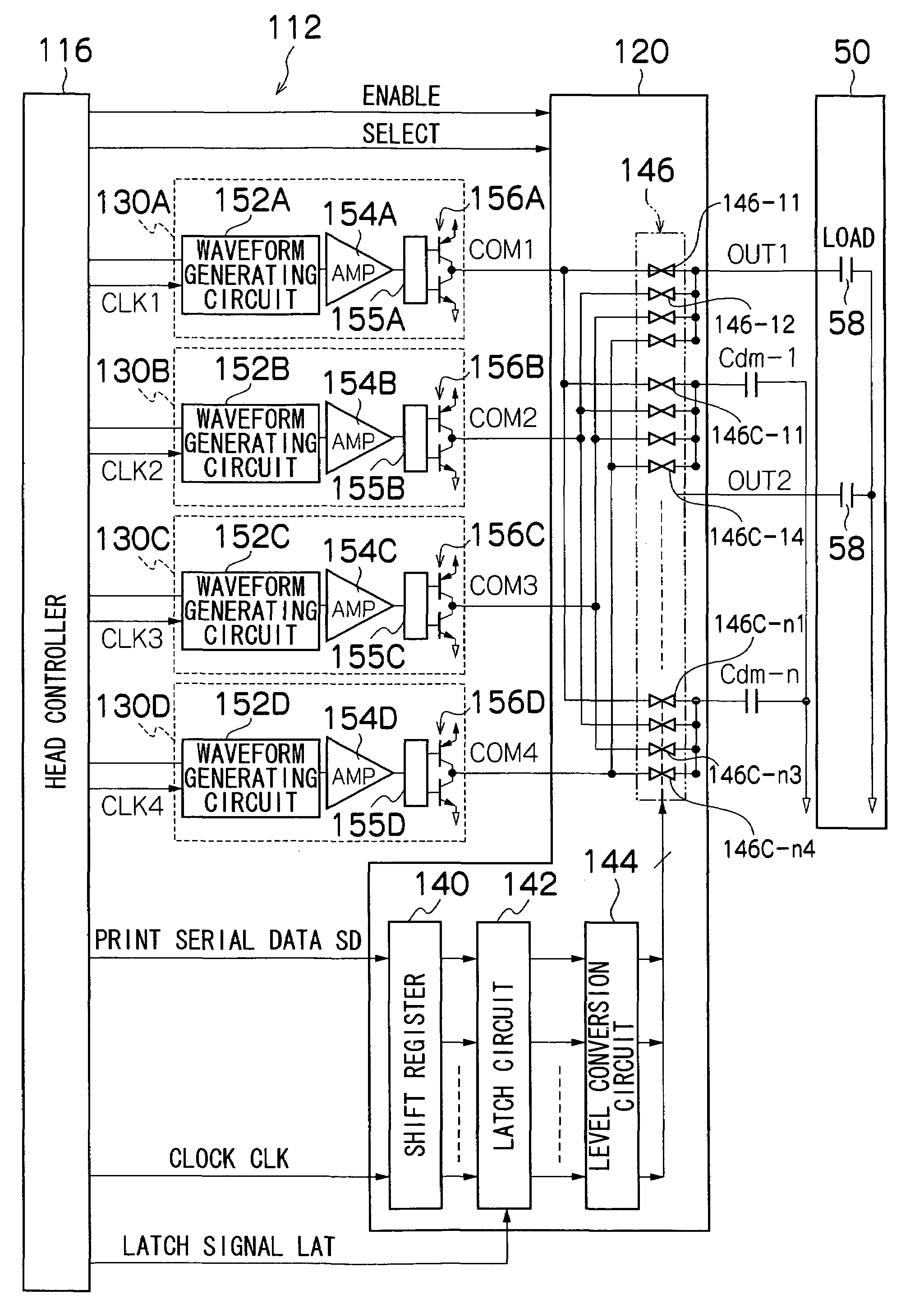
[0199]Then, the conditions of the main body of the inkjet recording apparatus 10 are determined (or the information thereof is acquired), so that information pertaining to the power source capacity, the number of drive circuits (four in the example in FIG. 9), and the like is obtained (step S110). The head conditions are determined (step S112), so that information pertaining to the state and type of the head, the ink conditions (for example, type and amount remaining), and the surroundings is obtain...

second embodiment

[0205]FIG. 15 is a flowchart showing the print control. The steps in FIG. 15 that are common to the flowchart in FIG. 14 are denoted with the same step numbers, and descriptions thereof are omitted. In the flowchart in FIG. 15, steps S118 through S126 in FIG. 14 are replaced by steps S130 through S134.

[0206]More specifically, a plurality of drive circuits are selected (step S130) and the phases of a plurality of driving waves are staggered (step S132) in accordance with the results of the instantaneous current consumption calculated in step S116 and the conditions of the image processing effects (ejection volume, ejection intervals, ejection times, deposition positions). Then, the instantaneous current consumption of the drive circuits is analyzed under these conditions, the instantaneous current consumption of the entire system is estimated, and the results of this calculation are compared with the power source capacity (i.e., the specific upper limit) (step S134).

[0207]If the resu...

third embodiment

[0209]FIG. 16 is a flowchart showing the print control. The steps in FIG. 16 that are common to the flowchart in FIG. 14 are denoted with the same step numbers, and descriptions thereof are omitted. In the flowchart in FIG. 16, steps S118 through S126 in FIG. 14 are replaced by steps S140 through S146.

[0210]More specifically, one of the plurality of drive circuits to apply the common driving wave to one of the nozzles is selected from the plurality of drive circuits according to the results of the instantaneous current consumption calculated in step S116 and the previous nozzle map history (step S140). For example, the drive circuit different from the drive circuit used in the previous ejection is selected.

[0211]Next, the calculated instantaneous current consumption is compared with the specific upper limit that has been set in accordance with the power source capacity (step S142), and if the instantaneous current consumption of the drive circuits to be used in total is estimated to...


PUM


Abstract

The image forming apparatus comprises: a liquid ejection head which includes a plurality of nozzles and a plurality of pressure generating elements provided correspondingly to the plurality of nozzles, the pressure generating elements being applied with drive signals to eject recording liquid from the corresponding nozzles; a plurality of driving wave generating circuits which generate drive-signal waves for driving the pressure generating elements; a circuit selecting device which selectively switches the driving wave generating circuits to apply the drive-signal waves to the pressure generating elements; a power source which supplies electricity to the pressure generating elements through the driving wave generating circuits; a connection control device which, in accordance with image data representing an image to be formed, selects at least one of the driving wave generating circuits used to drive the pressure generating elements, and controls connection between the at least one of the driving wave generating circuits and the pressure generating elements, so that instantaneous current consumption of each of the driving wave generating circuits falls within a specific allowable value; and a phase control device which controls phases of the drive-signal waves generated by the driving wave generating circuits so that the instantaneous current consumption at the power source falls within a specific upper limit.

Description

BACKGROUND OF THE INVENTION[0001]1. Field of the Invention[0002]The present invention relates to an image forming apparatus and a drive control method for a liquid ejection head, and particularly relates to an image forming apparatus that forms images using a liquid ejection head having pressure generating elements corresponding to multiple ejection ports (nozzles), and to a drive control technique for a liquid ejection head suitable for this apparatus.[0003]2. Description of the Related Art[0004]Generally, in inkjet recording apparatuses (inkjet printers), printing is performed by ejecting ink droplets from the nozzles of a recording head at specific timings on the basis of dot pattern data (also referred to as “dot data” or “print data”) resulting from the development of image data for printing inputted from a host computer, and depositing and sticking these ink droplets onto recording paper or another such print recording medium.[0005]A known example of a recording head system is...

Claims


Application Information

Patent Timeline
Patent Type & Authority Patents(United States)
IPC IPC(8): B41J29/38
CPCB41J2/0457B41J2/04581B41J2/04588B41J2/04593B41J2/04596
Inventor TAKATA, TAKUYA
Owner FUJIFILM CORP
Why Eureka
Try Eureka