Ammonia plant configuration and methods

a technology of ammonia plant and configuration method, which is applied in the direction of indirect heat exchangers, lighting and heating apparatus, chemical production, etc., can solve the problems of cloning a few inefficient ammonia plants, and affecting the efficiency of ammonia plants

Inactive Publication Date: 2008-10-28
FLUOR TECH CORP
View PDF10 Cites 3 Cited by
  • Summary
  • Abstract
  • Description
  • Claims
  • Application Information

AI Technical Summary

Benefits of technology

[0017]In another particularly preferred aspect of the inventive subject matter, contemplated plants may include a pressure swing absorption unit that receives a first portion of a feed gas having a molar ratio of hydrogen to nitrogen of less

Problems solved by technology

The relatively high price of natural gas has recently resulted in the closure of a few inefficient ammonia plants in the US.
While Grotz's configuration is relatively effective in some ammonia production plants, retrofitting of existing plants is relatively problematic since the expansion step requires considerable increase in front-end pressure in a ammonia synthesis plant (and thereby typically necessitating retrofits/rebuilds to accommodate for th

Method used


Image

  • Ammonia plant configuration and methods
  • Ammonia plant configuration and methods
  • Ammonia plant configuration and methods

Examples


Embodiment Construction

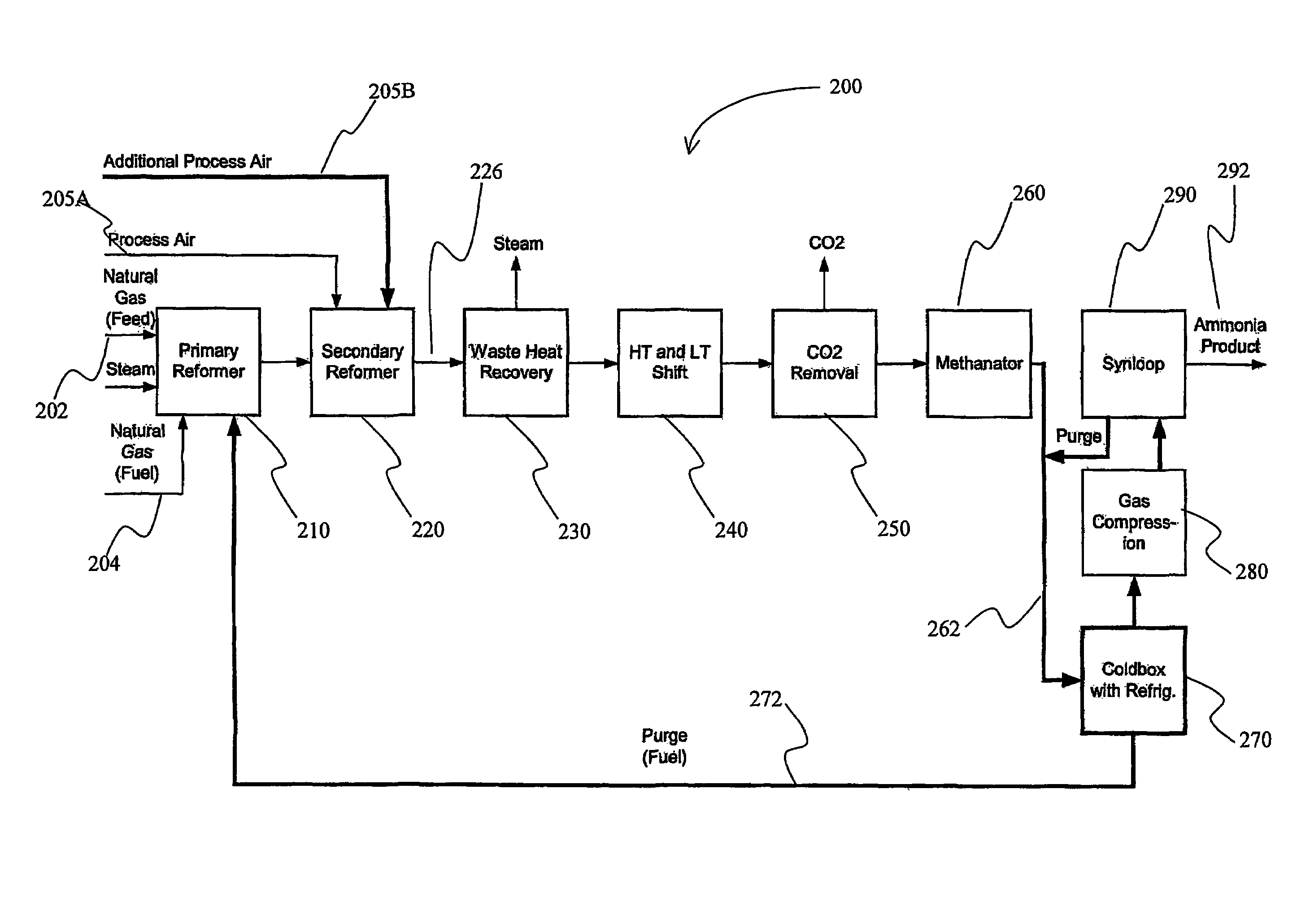
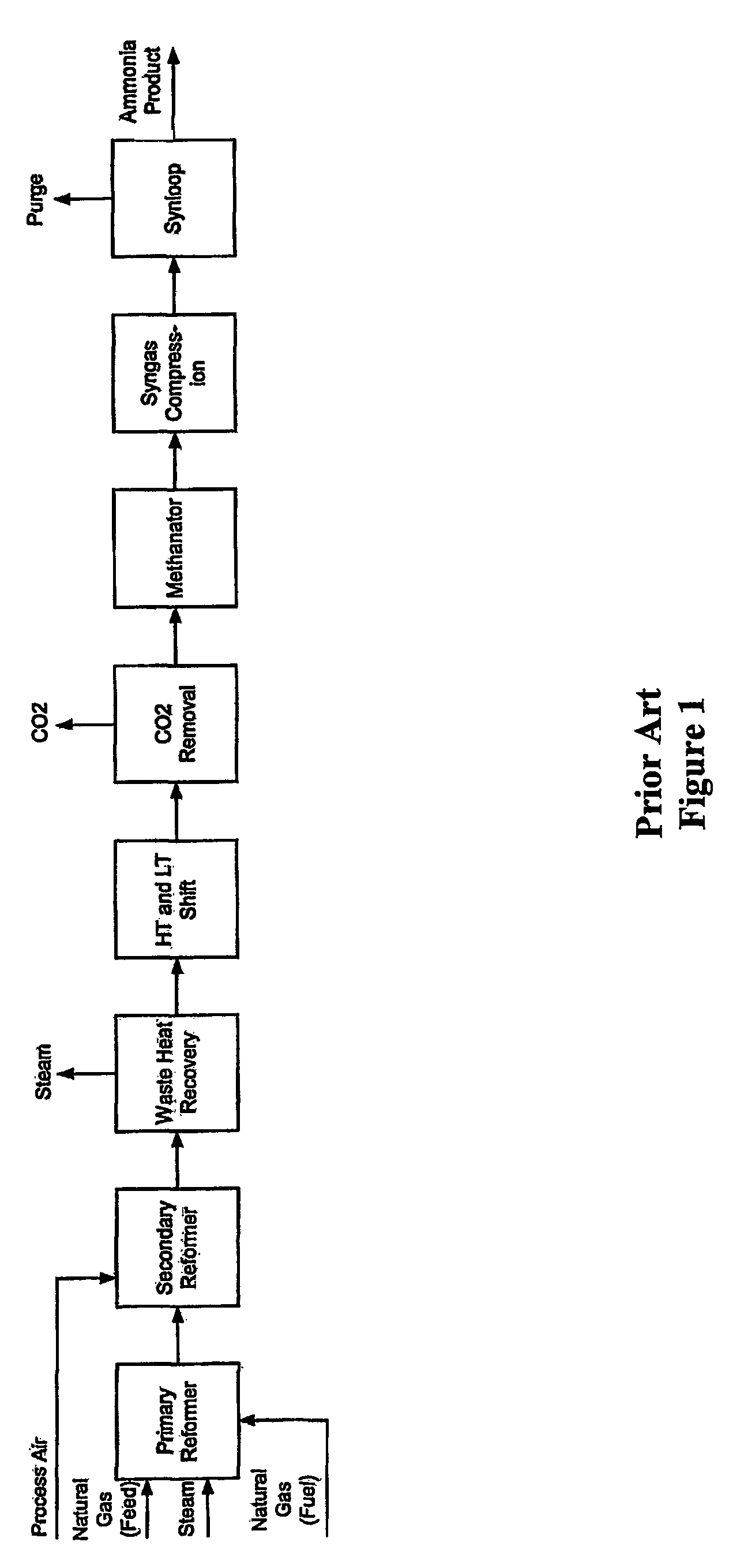
[0020]The majority of ammonia plants operating today use a stoichiometric amount of process air in the secondary reformer in order to maintain a hydrogen to nitrogen molar ratio of 3 to 1 in the methanator effluent gas, which is typically the make-up gas to the ammonia synthesis loop.

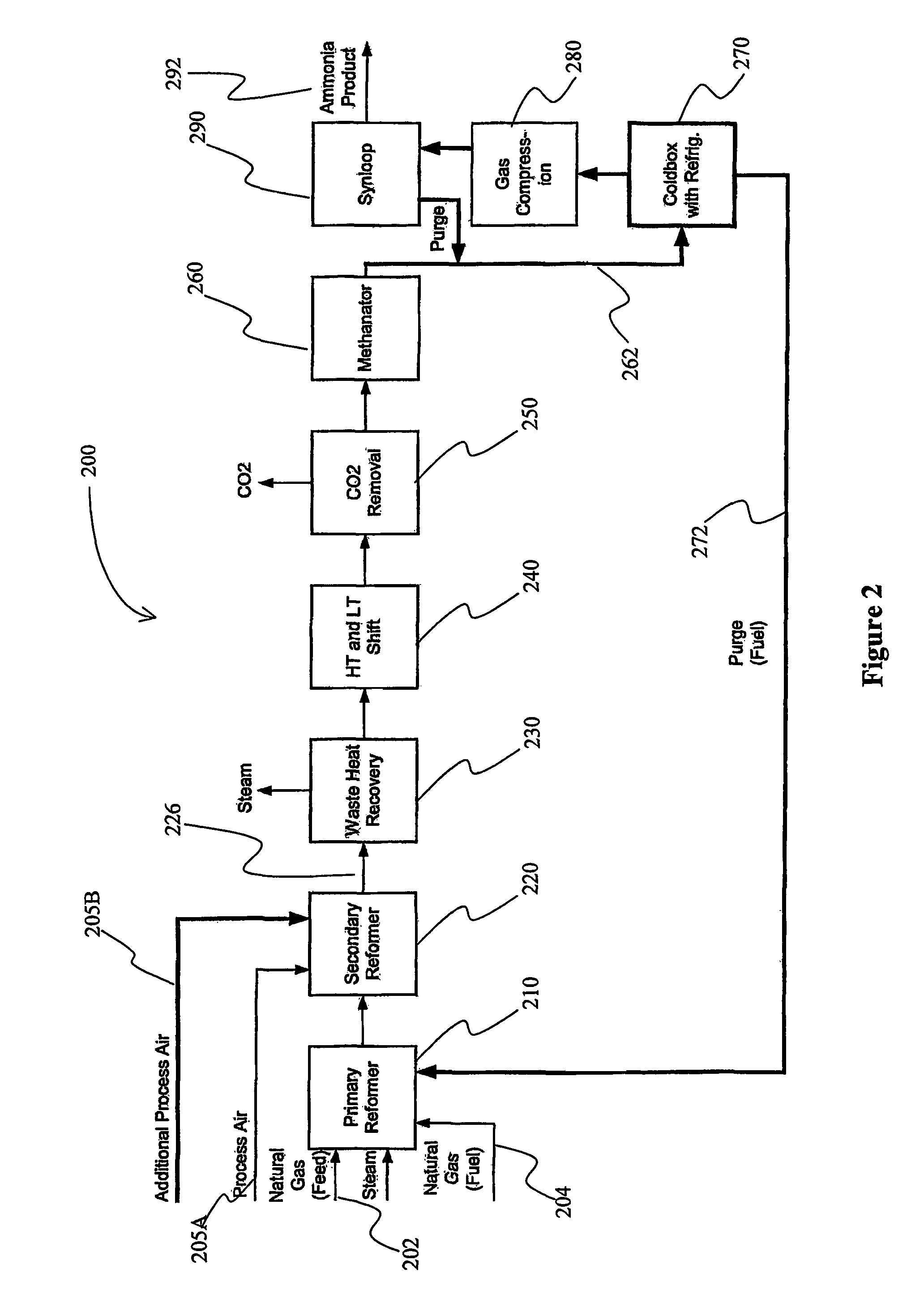
[0021]The inventors have discovered that a separation system, and most preferably a coldbox or pressure swing absorption (PSA) system can advantageously be integrated in an ammonia production plant (e.g., installed downstream of a methanator to process the methanator effluent gas before it enters the ammonia synthesis loop), thereby increasing the production capacity and / or reducing the energy requirements. Thus, excess air and / or nitrogen can be introduced to the front-end of the syngas production process to improve capacity in contemplated configurations, while maintaining the stoichiometric ratio of hydrogen to nitrogen at about 3:1. The term “a molar ratio of hydrogen to nitrogen of about 3.0” as us...


PUM


Abstract

A synthesis plant includes a separation system upstream of a synthesis loop that removes excess nitrogen and other gaseous compounds from a feed gas having a ratio of hydrogen to nitrogen of less than 3:1, thereby producing a syngas with a ratio of hydrogen to nitrogen at about 3:1. Particularly preferred separation systems include a coldbox with a refrigerant other than air, or a pressure swing absorption system.

Description

[0001]This application claims priority to U.S. provisional patent application with the Ser. No. 60 / 302,055, which was filed on Jun. 28, 2001 and is incorporated by reference herein.BACKGROUND OF THE INVENTION[0002]The relatively high price of natural gas has recently resulted in the closure of a few inefficient ammonia plants in the US. To make matters worse, natural gas prices are expected to remain high in the foreseeable future. Thus, for ammonia plants to become and remain profitable, it will be imperative to increase revenue and reduce operating costs. Viewed from another perspective, plants will have to find ways to increase production and reduce their energy consumption per ton of ammonia produced.[0003]In a typical prior art plant configuration as depicted in Prior art FIG. 1, natural gas is processed through primary and secondary reformers, and the reformed gas stream is then subjected to a shift conversion after excess heat has been recovered from the reformed gas stream. ...

Claims


Application Information

Patent Timeline
IPC IPC(8): B01J19/00C01B3/02C01B3/38C01B13/02C01C1/02C01C1/04F25J3/02
CPCC01B3/025C01B3/382C01B13/0248C01C1/0405C01C1/0476F25J3/0219F25J3/0276F25J3/04539F25J3/04587C01B2203/00C01B2203/0233C01B2203/0244C01B2203/0288C01B2203/0415C01B2203/043C01B2203/0445C01B2203/047C01B2203/0475C01B2203/06C01B2203/068C01B2203/0844C01B2203/0883C01B2203/0894C01B2203/1241C01B2203/142C01B2203/143C01B2203/146C01B2203/147C01B2203/82C01B2210/0046F25J2200/02F25J2200/74F25J2200/80F25J2210/20F25J2245/02F25J2245/42F25J2270/02F25J2270/04F25J2270/14F25J2270/42F25J2290/80Y02P20/52F25J2270/88F25J2270/902Y02P20/50
Inventor REDDY, SATISHBHAKTA, MUKUNDVYAS, SUNIL
Owner FLUOR TECH CORP
Why Eureka
Try Eureka