
Apparatus for removable distal internal cassette for in situ fixation and specimen processing with serial collection and storage of biopsy specimens

a technology of in situ fixation and biopsy specimen, which is applied in the field of apparatus for serial collection, storage and processing of biopsy specimen, can solve the problems of inability to retrieve samples by catheterization method using endoscopic or fluoroscopic control, inability to use blind palpation, and frequent loss of minute specimens, so as to avoid the risk

Active Publication Date: 2008-11-04
ZIMMON DAVID S
View PDF16 Cites 22 Cited by
  • Summary
  • Abstract
  • Description
  • Claims
  • Application Information

AI Technical Summary

Benefits of technology

"The present invention provides a simple and convenient cassette for collecting, storing, and processing biopsy specimens. The cassette can be used with a flexible biopsy instrument and is designed to be easily detached from the instrument. The cassette allows for easy handling and provides a convenient way to process the collected biopsy specimens. The cassette can be used for fixation, processing, staining, or tissue testing, and can be transparent for immediate inspection and analysis of the biopsies. The invention also allows for fluid sampling or injection for irrigation, injection of radiopaque contrast, or tissue stains."

Problems solved by technology

These samples can only be retrieved by catheterization methods using endoscopic or fluoroscopic control, or by blind palpation.
During this process of acquisition and collection minute specimens were frequently lost and are always contaminated by handling and passage through the endoscope instrument channel.
Furthermore during acquisition the staff is exposed to potentially infectious human tissue and toxic fixatives.
The biopsies obtained in each pass were processed in a batch, since the minute pieces could not be easily separated.
Multiple biopsy passes were required because of the limited storage capacity of the biopsy instruments and the need to identify the origin of each biopsy sites.
Consequently, biopsies from different anatomic sites were handled separately, thus requiring considerable effort and expense.
This prolonged the procedure and could cause it to fail, if the position of the biopsy instrument could not be reacquired during the repeated passes of the biopsy instrument through the endoscope.
This complexity prolonged the endoscopic procedure and increased the quantity of sedative administered to the patient, risk and cost.
During this complex handling process, small specimens may be lost or damaged.
At each stage of handling, the staff is exposed to infection from the biopsies and fixative.
This tedious, labor intensive process is expensive in staff required, time, equipment and laboratory space.
These specimens were contaminated by fluid and tissue in the track traversed to obtain the biopsies and within the channel of the endoscopic instrument.
The delay in acquisition and contamination of the specimens limit the accuracy and reliability of the subsequent analysis.
This disability may be severe when genetic or biological testing is needed.
This action moves the endoscope and biopsy device away from the biopsy site, limits maneuverability and prevents rapid serial biopsy of the target site.
This stiffness and uncontrolled motion also risks trauma to the biopsy site and limits access in curved lumens.
A further limitation of stiff shafts is that they reduce the options for carrier instrument flexibility and maneuverability.
Furthermore, tissue distortion from biopsy trauma makes histopathologic interpretation difficult because of crush and shear artifacts.
These artifacts result in false positive and false negative histopathologic interpretations of biopsy specimens leading to an incorrect diagnosis.

Method used


Image

  • Apparatus for removable distal internal cassette for in situ fixation and specimen processing with serial collection and storage of biopsy specimens
  • Apparatus for removable distal internal cassette for in situ fixation and specimen processing with serial collection and storage of biopsy specimens
  • Apparatus for removable distal internal cassette for in situ fixation and specimen processing with serial collection and storage of biopsy specimens

Examples


Embodiment Construction

[0029]For purposes of promoting an understanding of the principles of the invention reference will now be made to the embodiment illustrated in the drawings and specific language will be used to describe the same. It will nevertheless be understood that no limitation of the scope of the invention is thereby intended, such alterations and further modifications in the illustrated device, and such further applications of the principles of the invention as illustrated therein being contemplated as would normally occur to one skilled in the art to which the invention relates.

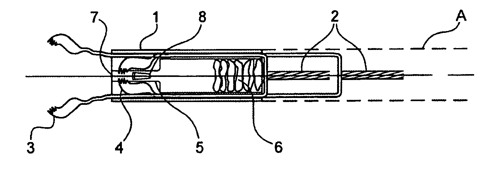
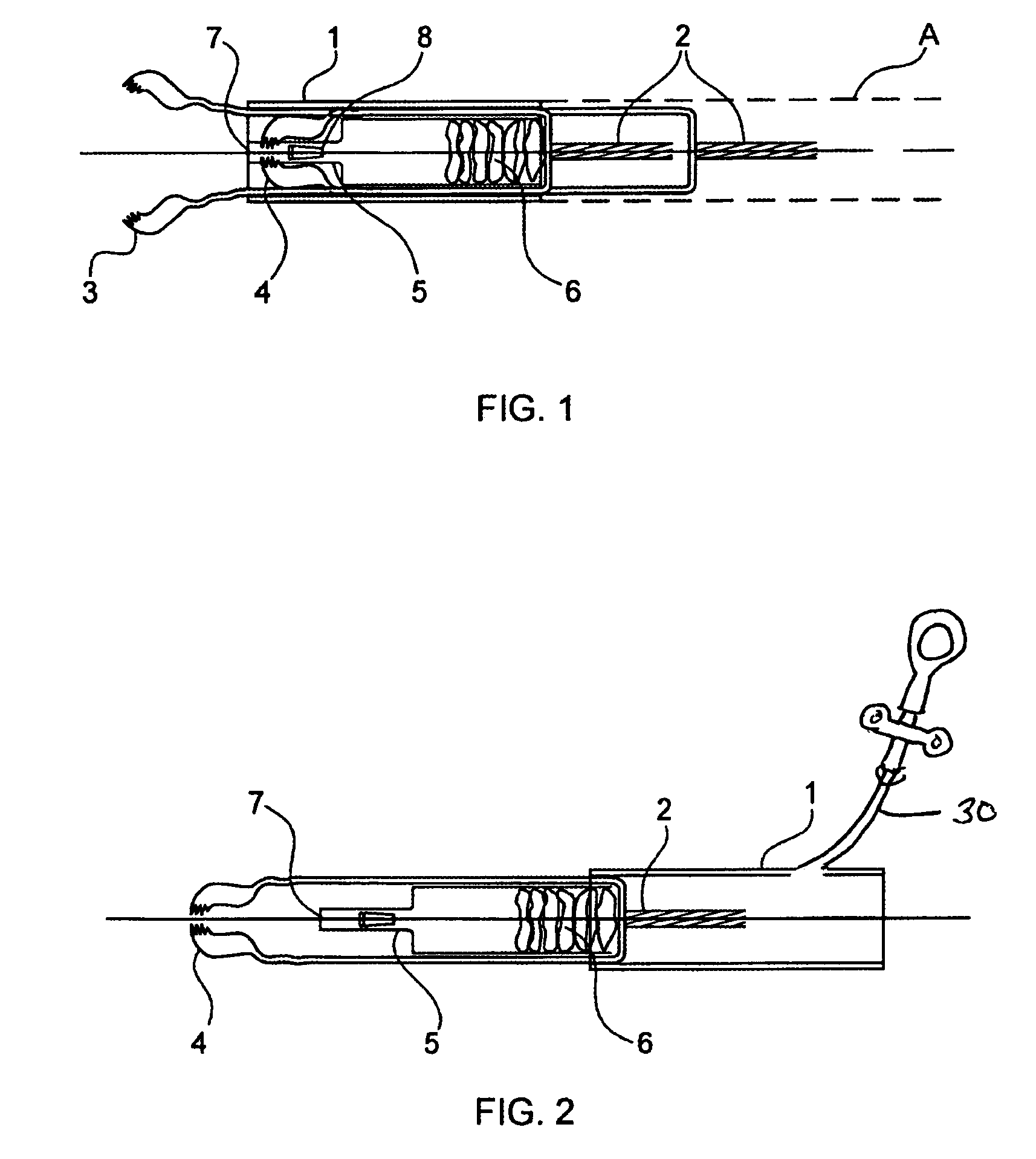
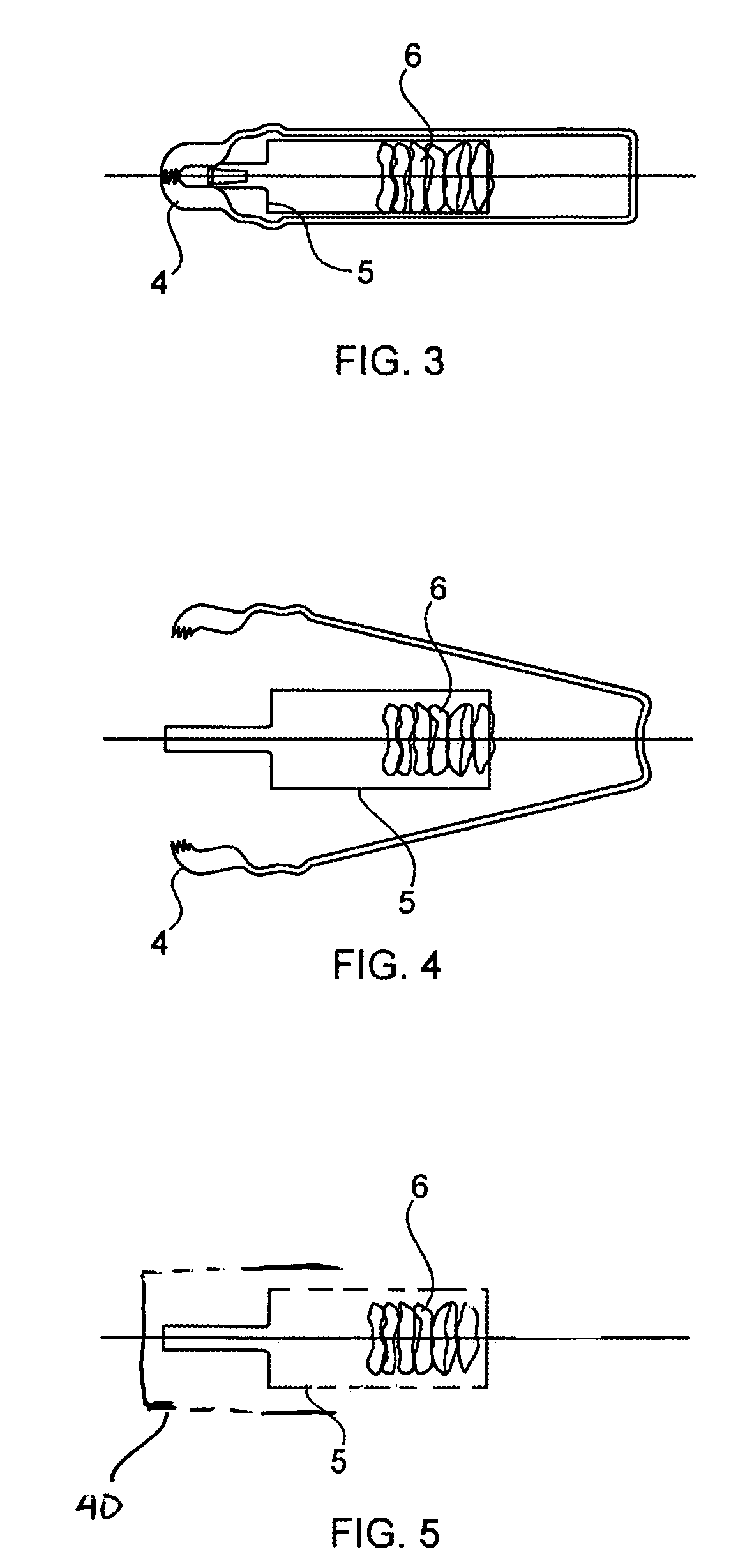
[0030]FIGS. 1 and 2 show the device according to the invention, which retrieves specimens 6 through a spring-based biopsy cutting tool 3. Cutting tool 3 is connected to the central actuator wire arranged inside a catheter tip tube 1, which has two short side slots and a large central lumen. The tip tube is removably connected to the longer tube shaft (A) containing the actuator wire that extends proximally to the han...


PUM


Abstract

An apparatus for performing a medical procedure comprises an elongated flexible member having an aperture extending longitudinally therethrough and an actuator positioned within the aperture. There is a biopsy means connected to the distal end of the actuator for cutting and collecting biopsy specimens and a removable distal storage and collection chamber connected to the elongated flexible member for receiving biopsy specimens cut and collected by the biopsy means. The removable storage and collection chamber is a means for immediate contact of the collected biopsy specimens with fixatives or reagents. The distal cassette is separable from the flexible member and can be sealed by a cap positionable over the storage and collection cassette for storage, in situ fixation and processing or later processing and analysis of biopsy specimens collected by the biopsy means in the order of collection.

Description

BACKGROUND OF THE INVENTION[0001]1. Field of the Invention[0002]The present invention relates to an apparatus for serial collection, storage and processing of biopsy specimens. The device cuts and captures a biopsy specimen with a closely defined size to permit serial entry into a removable distal storage cassette for in situ chemical, biological or genetic testing by immediately reacting with the biopsy specimens before metabolic changes, degradation or contamination can occur or for fixation, staining and other processing and analysis. The cassette may be optically transparent for physical analysis of the tissue without removal from the cassette after separation from the biopsy instrument. Prior to biopsy the open tube shaft with a side arm permits fluid sampling, irrigation, and injection of tissue stains or radiopaque contrast agents.[0003]2. The Prior Art[0004]It is often necessary to obtain tissue samples for examination from deep within structures. These samples can only be r...

Claims


Application Information

Patent Timeline
Patent Type & Authority Patents(United States)
IPC IPC(8): A61B10/00A61B17/00A61B10/02A61B10/06A61B17/28A61B17/42A61B17/44
CPCA61B10/06A61B10/0096A61B2010/0225
Inventor ZIMMON, DAVID
Owner ZIMMON DAVID S
Learn More