Transmission line with low dispersive properties and its application in equalization

a transmission line and low dispersion technology, applied in line-transmission details, waveguides, baseband system details, etc., can solve the problems of high line loss, difficult to achieve such a condition, transmission lines, etc., and achieve the effect of restoring the gain of attenuated signals

Active Publication Date: 2008-11-04
INFINERA CORP
View PDF16 Cites 17 Cited by
  • Summary
  • Abstract
  • Description
  • Claims
  • Application Information

AI Technical Summary

Benefits of technology

[0017]A particular application for such a micro transmission line is in an IC chip where a multi-millimeter transmission line is utilized in an equalizer circuit deployed in a telecommunication network, such as, for example, in optical telecommunication systems employing a feed forward equalizer (FFE) in the optical receiver. However, the employment of this invention may be applied to other applications where there is a requirement to achieve a constant characteristic impedance in a transmission line at such lower signal frequencies or lower signal linewidth frequency components and adjustments can be readily made by adding either lump shunt resistance or distributed shunt resistance to a micro transmission lines or other such transmission lines acceptable or are capable of receiving series and shunt resistance design changes.

Problems solved by technology

On the other hand, when the signal frequency is very high, such as in the cases of multiple GHz range, serious skin effect can result in the transmission line resulting high line losses.
It has been suggested by those skilled in the art that setting LG=RC is best accomplished by increasing either L or C, rather than by increasing R or G because increasing the series resistance and / or shunt resistance provides an undesirable effect of increased transmission line attenuation.
However, it is difficult to achieve such a condition with a broadband signal which has frequency components practically down to DC or zero frequency.
This complex nature and frequency dependency nature of the characteristic impedance causes a propagation group velocity delay (GVD) of the signal traveling along the transmission line and, thus, the line is unacceptably dispersive.

Method used


Image

  • Transmission line with low dispersive properties and its application in equalization
  • Transmission line with low dispersive properties and its application in equalization
  • Transmission line with low dispersive properties and its application in equalization

Examples


Embodiment Construction

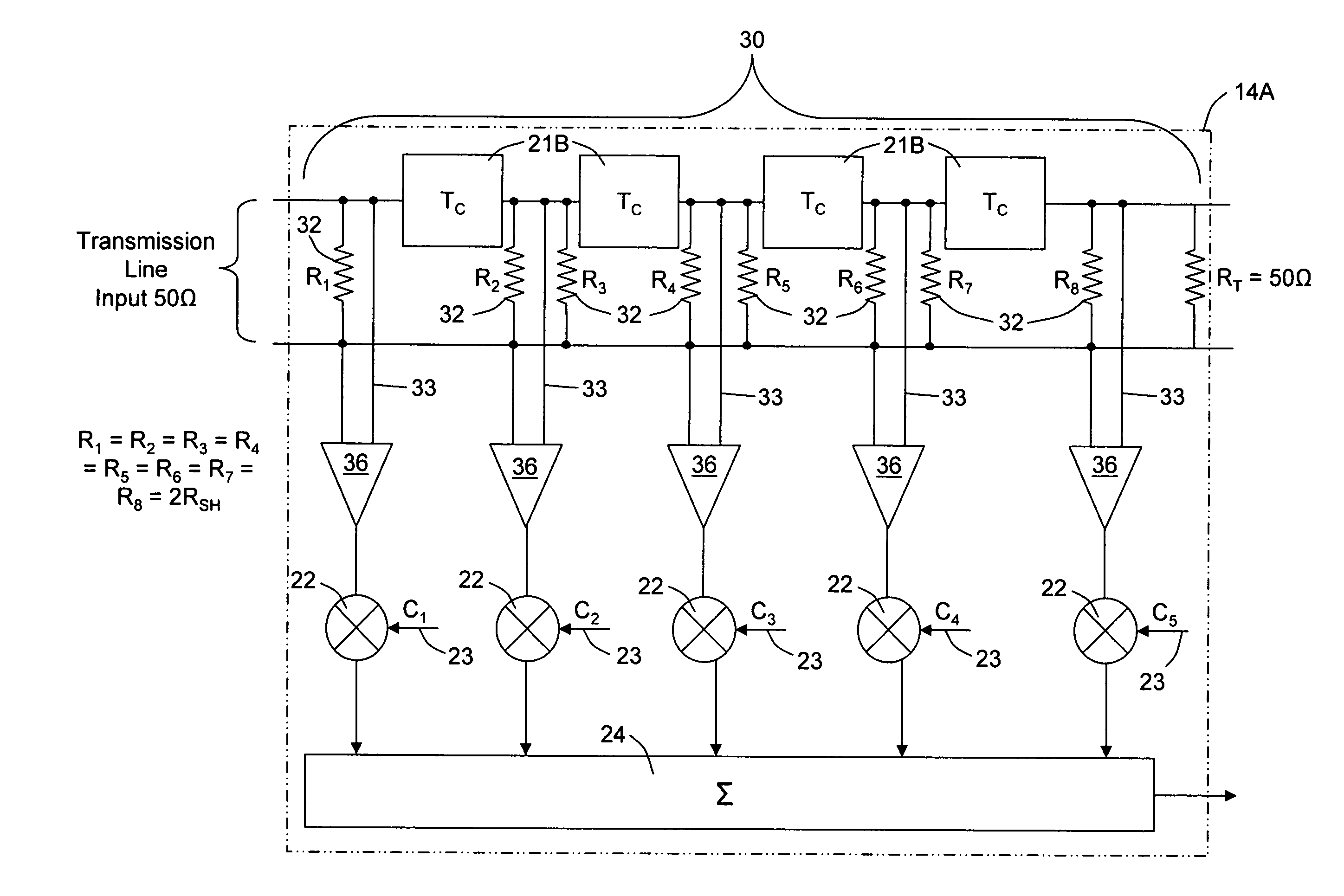
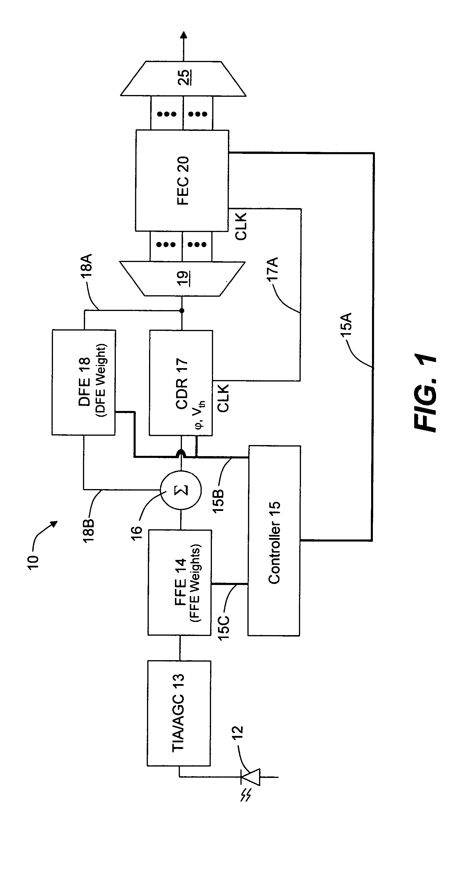
[0026]Reference is now made to FIG. 1 which illustrates a block diagram of an optical receiver 10 that may be utilized in connection with this invention. It will be appreciated by those skilled in the art that the application of a micro transmission line according to this invention may be employed in other applications, other then an optical receiver, for example, any application utilizing an analog feed forward equalizer (FFE), in any signal detection and / or recovery application, or any analog signal processing application requiring the use of a signal delay line as well as in transmission lines formed on PCBs, ICs or other analog transmission line circuits were the values of equation (1) may be adjusted in a practical manner in designing such transmission line circuits.

[0027]Optical receiver 10 has a signal path that includes photodetector 12 where the optical signal is converted into a current signal, the amplitude of which is representative of the optical pulses of the incoming ...


PUM


Abstract

A transmission line is provided with added shunt resistance, RSH, distributed along the length of the micro transmission line permitting the extension of constant characteristic impedance to the transmission line to lower signal frequencies. The loss in gain to the signal propagating the transmission line due to the added resistance can be compensated for by amplification provided at the output of the transmission line or at output taps provided along the length of the transmission line such as in cases where the line is utilized as a circuit delay line. An exemplified application disclosed is an analog delay line formed as a metal microstrip in an IC chip circuit provided, for example, in a feed forward equalizer (FFE).

Description

REFERENCE TO A RELATED APPLICATION[0001]This application claims priority of U.S. provisional application Ser. No. 60 / 500,523, filed Sep. 5, 2003, which application is incorporated herein by reference in its entirety.BACKGROUND OF THE INVENTION[0002]1. Field of the Invention[0003]This invention relates generally to impedance balanced transmission lines and more particularly to micro or microstrip transmission lines, such as, for example, fabricated in integrated circuits (ICs) or formed on PCBs.[0004]2. Description of the Related Art[0005]The application of high frequency transmission lines in integrated circuits (ICs) or in LSI circuits is known. The characteristic impedance of such transmission lines follows the well known module equation per equation (1) below:Zo=√{square root over ((R+jωL) / (G+jωC))}{square root over ((R+jωL) / (G+jωC))}  (1)[0006]R is series resistance per unit length (Ω / mm or cm), G is the shunt (parallel conductance) Sieman per unit length (S / mm or in cm), L is t...

Claims


Application Information

Patent Timeline
Patent Type & Authority Patents(United States)
IPC IPC(8): H04B3/04H01P3/08
CPCH01P3/081H01P3/085H04B3/04
Inventor CHIANG, TING-KUANG
Owner INFINERA CORP
Why Eureka
Try Eureka