
Calibration of digital diagnostics information in an optical transceiver prior to reporting to host

a technology of optical transceivers and diagnostic information, applied in the field of optical transceivers and optical transceiver host computing systems, can solve the problems of many hosts not being able to access enough samples for reliable calibration, and digital samples may contain predictable errors, so as to save valuable host computing resources, faster communication channels, and the effect of accelerating the processing speed

Active Publication Date: 2008-11-04
II VI DELAWARE INC
View PDF117 Cites 2 Cited by
  • Summary
  • Abstract
  • Description
  • Claims
  • Application Information

AI Technical Summary

Benefits of technology

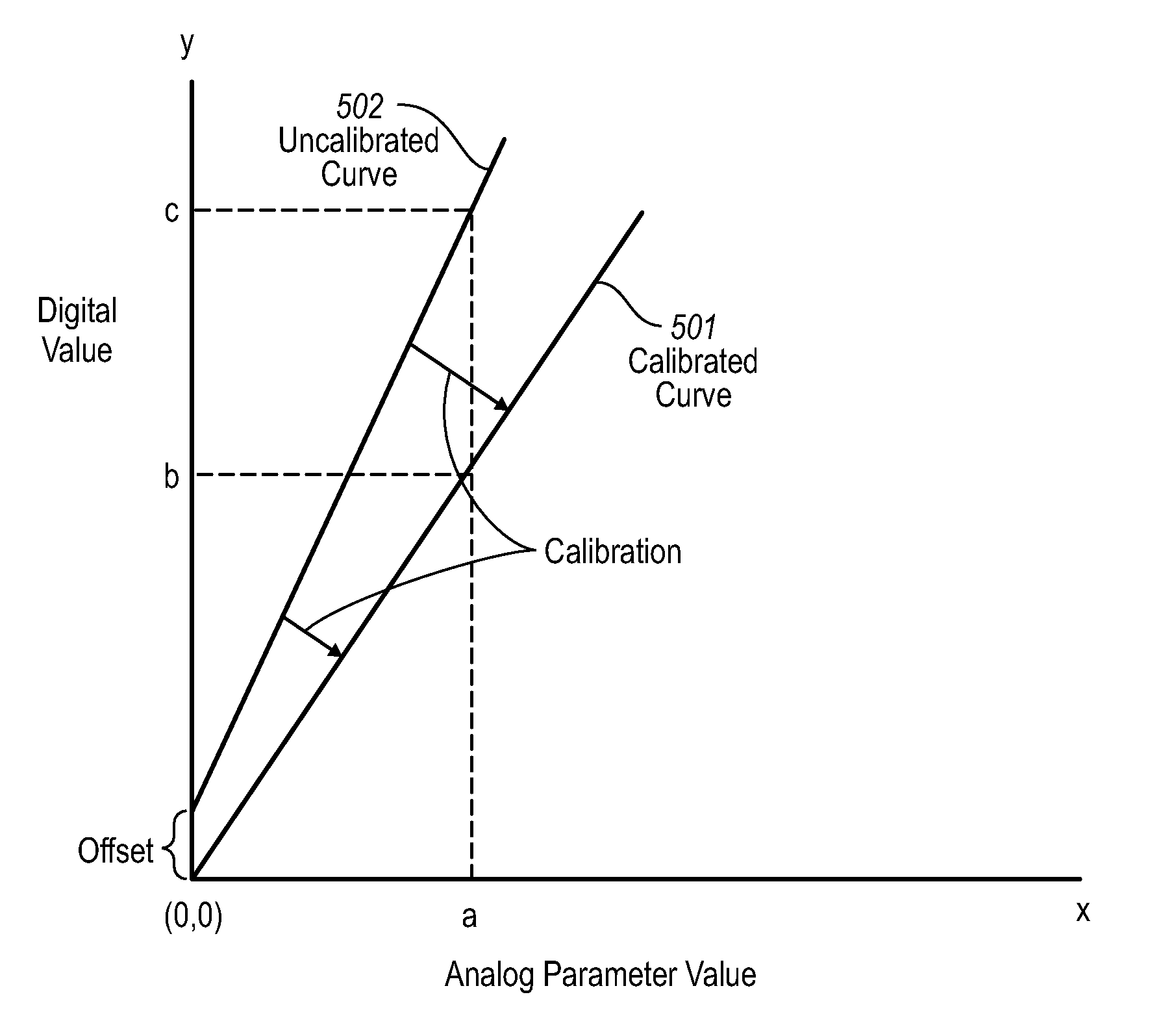
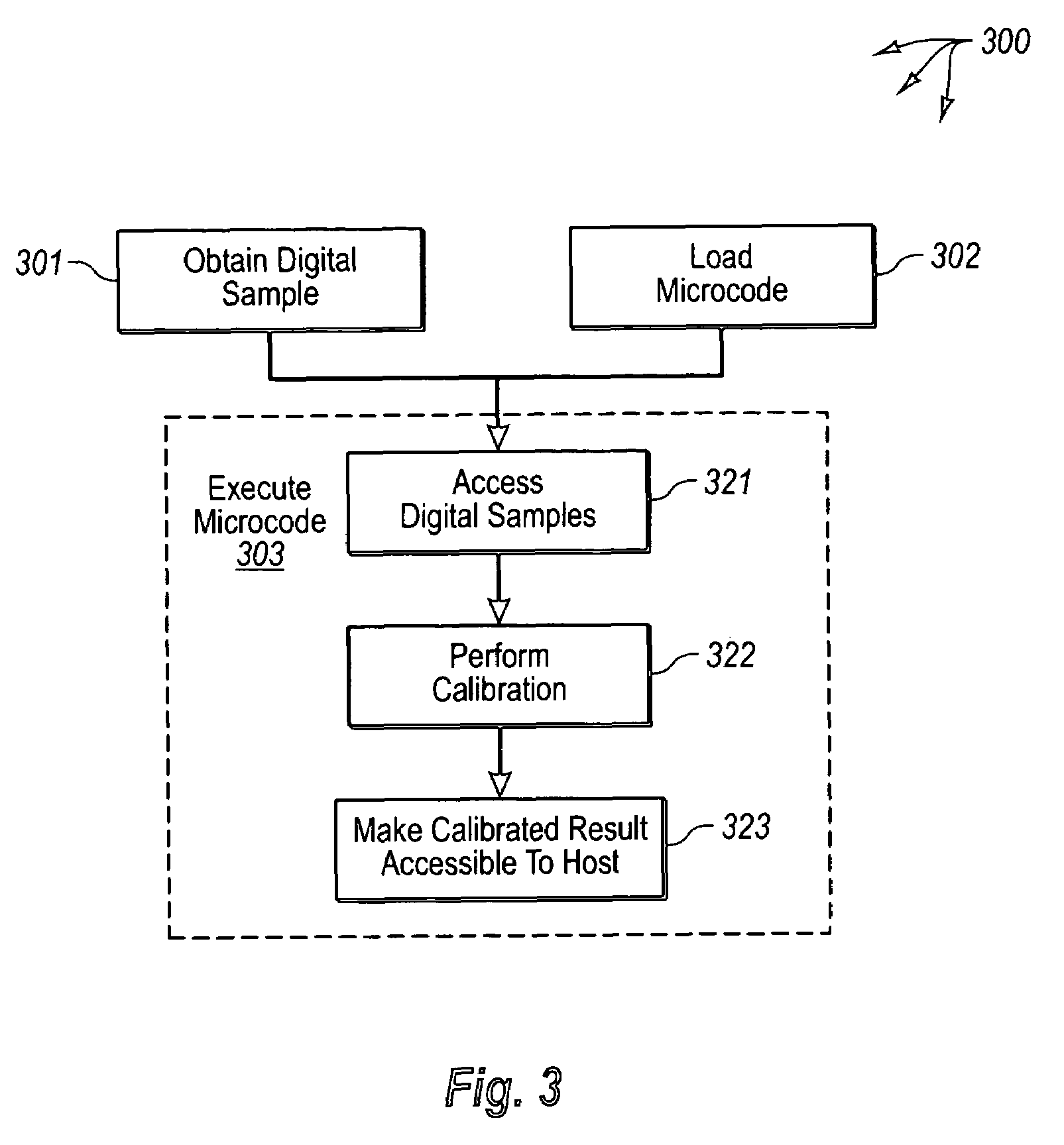
[0016]Specifically, microcode is loaded into the system memory. The microcode, when executed by the at least one processor, causes the optical transceiver to perform a calibration operation on the digitally converted samples to remove the predictable error. The execution of the microcode causes the optical transceiver to enforce calibration rules in order to perform the calibration. The transceiver may then make the calibrated results accessible to the host.
[0017]Accordingly, the principles of the present invention provide for calibration of digital diagnostic information prior to the transceiver making the digital diagnostics information accessible to the host. This saves valuable host computing resources for other host operations. In addition, many hosts are not able to access enough samples for reliable calibration. This may be due to slower communication channels between the host and transceiver. Since the optical transceiver is able to access the samples more quickly and efficient, and since the optical transceiver itself performs the calibration, the calibration likewise is much more efficient.

Problems solved by technology

However, the digital samples may often contain predictable error from the analog-to-digital conversion or perhaps from other components the sense or process the analog signals prior to arriving at the analog-to-digital converter.
In addition, many hosts are not able to access enough samples for reliable calibration.
This may be due to slower communication channels between the host and transceiver.

Method used


Image

  • Calibration of digital diagnostics information in an optical transceiver prior to reporting to host
  • Calibration of digital diagnostics information in an optical transceiver prior to reporting to host
  • Calibration of digital diagnostics information in an optical transceiver prior to reporting to host

Examples


Embodiment Construction

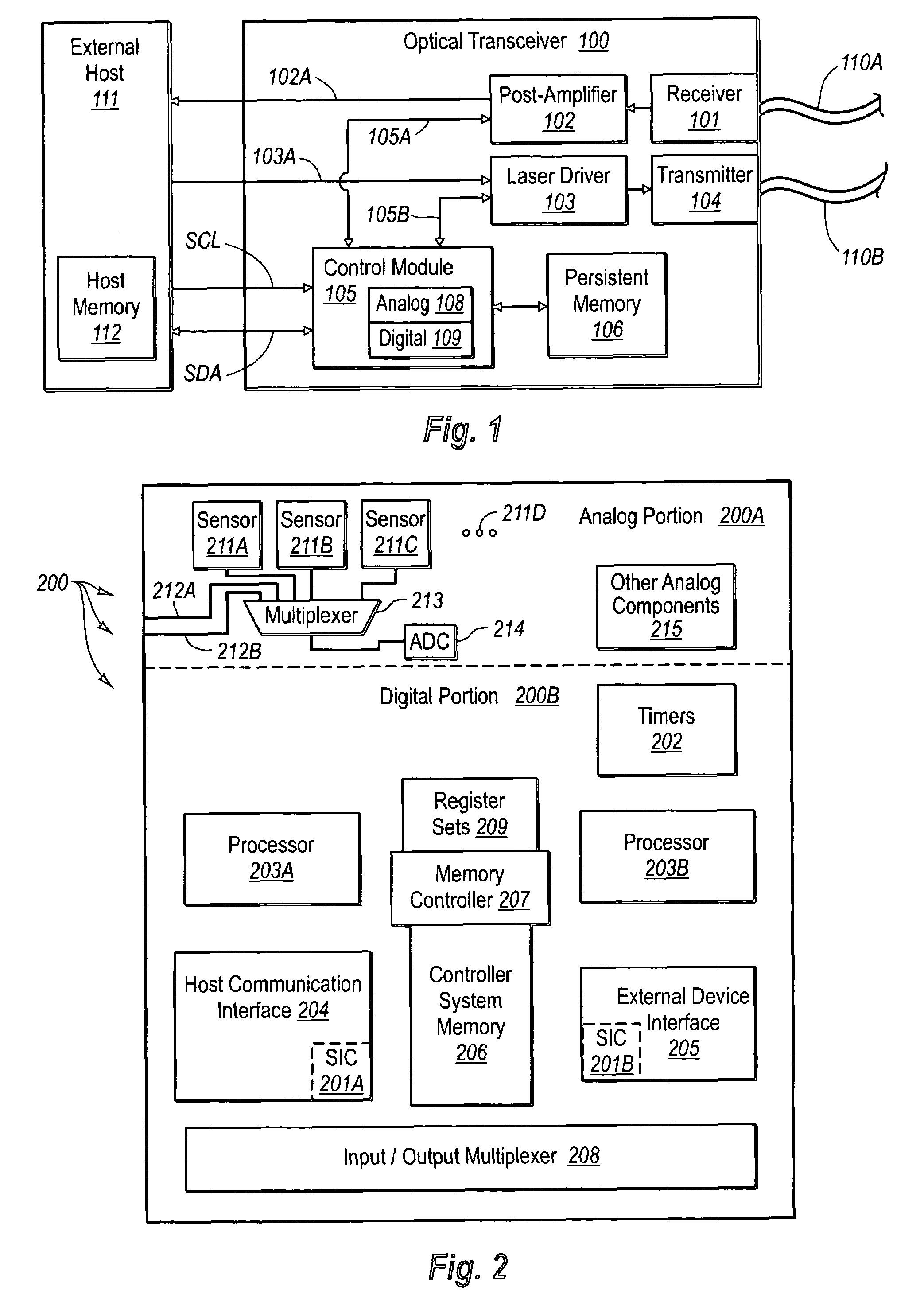
[0025]The principles of the present invention relate to an optical transceiver configured to perform calibration of digital diagnostics prior to providing the calibrated values to a host computing system (hereinafter referred to simply as a “host”) that is communicatively coupled to the optical transceiver. The optical transceiver includes a sensor that measures an analog operational parameter signal such as temperature or supply voltage. Each analog signal is then converted to digital samples by analog to digital converter(s). A processor executes microcode that causes the optical transceiver to perform calibration on the various samples to compensate for predictable error introduced into the analog signal prior to or during the analog-to-digital conversion. The optical transceiver may then make the calibrated result accessible to the host. This may be accomplished by the host polling the transceiver for calibrated results and / or by the transceiver directly logging the calibrated r...


PUM


Abstract

An optical transceiver configured to perform calibration of digital diagnostics prior to providing the calibrated values to a host computing system (hereinafter referred to simply as a “host”) that is communicatively coupled to the optical transceiver. The optical transceiver includes a sensor that measures an analog operational parameter signal such as temperature or supply voltage. Each analog signal is then converted to digital samples by analog to digital converter(s). A processor executes microcode that causes the optical transceiver to perform calibration on the various samples to compensate for predictable error introduced into the analog signal prior to or during the analog-to-digital conversion. The optical transceiver may then make the calibrated result accessible to the host.

Description

CROSS-REFERENCE TO RELATED APPLICATIONS[0001]This application claims the benefit of U.S. Provisional Application No. 60 / 585,254, filed Jul. 2, 2004, which is incorporated herein by reference in its entirety.BACKGROUND OF THE INVENTION[0002]1. The Field of the Invention[0003]The present invention relates generally to optical transceivers and optical transceiver host computing systems (hereinafter referred to simply as “host”). More specifically, the present invention relates to calibrating digital diagnostic information of the optical transceiver prior to reporting the calibrated information to the host.[0004]2. The Relevant Technology[0005]Computing and networking technology have transformed our world. As the amount of information communicated over networks has increased, high speed transmission has become ever more critical. Many high speed data transmission networks rely on optical transceivers and similar devices for facilitating transmission and reception of digital data embodie...

Claims


Application Information

Patent Timeline
Patent Type & Authority Patents(United States)
IPC IPC(8): H04B10/00H03M1/10H04B10/69
CPCH03M1/1028H04B10/695H03M1/1235
Inventor EKKIZOGLOY, LUKE M.HAHIN, JAYNE C.DYBSETTER, GERALD L.NELSON, STEPHEN
Owner II VI DELAWARE INC
Learn More