
Exhaust system for an engine

a technology of exhaust system and engine, which is applied in the direction of engine components, machines/engines, mechanical apparatus, etc., can solve the problems of affecting the usable life or durability of the catalyst, and so as to reduce the effect of reducing the usable life of the catalys

Inactive Publication Date: 2008-11-11
YAMAHA MOTOR CO LTD
View PDF25 Cites 15 Cited by
  • Summary
  • Abstract
  • Description
  • Claims
  • Application Information

AI Technical Summary

Benefits of technology

The patent text discusses techniques for improving the performance and durability of exhaust gas purifiers in engines. The technical effects of the patent include controlling the introduction of secondary air in the exhaust pipe to prevent damage to the catalysts and improving the activation temperature of the catalysts to optimize their purification performance in cold operating conditions. The patent also describes a method for controlling the temperature difference between adjacent catalysts to prolong their life and minimize the impact of temperature differences on the purification burden. Overall, the patent provides solutions for enhancing the performance and durability of exhaust gas purifiers in engines.

Problems solved by technology

However, introduction of secondary air into the exhaust pipe in the conventional engine may reduce the usable life of the catalysts.
In some cases, the location of the introduction secondary air is a factor that affects the usable life or durability of the catalyst.
In some cases, elevated or excessive temperatures affect the life of a catalyst.
For example, if the catalysts are excessively heated by the introduction of the secondary air, the catalysts can deteriorate, reducing the usable life thereof.
Also, deterioration of the catalyst can occur more quickly if the high temperature state persists for a long time.
The performance of an exhaust gas purifier also can be hindered in cold operating conditions by introduction of secondary air.
Accordingly, the removal of CO and HC by the downstream catalyst is less than optimal in this situation.
In exhaust gas purifiers where multiple catalysts are used, each of the catalysts contribute a portion of the purification of the exhaust gas, or exhaust gas purification burden.
As a result, the catalyst carrying the greater burden may deteriorate more quickly.

Method used


Image

  • Exhaust system for an engine
  • Exhaust system for an engine
  • Exhaust system for an engine

Examples


Embodiment Construction

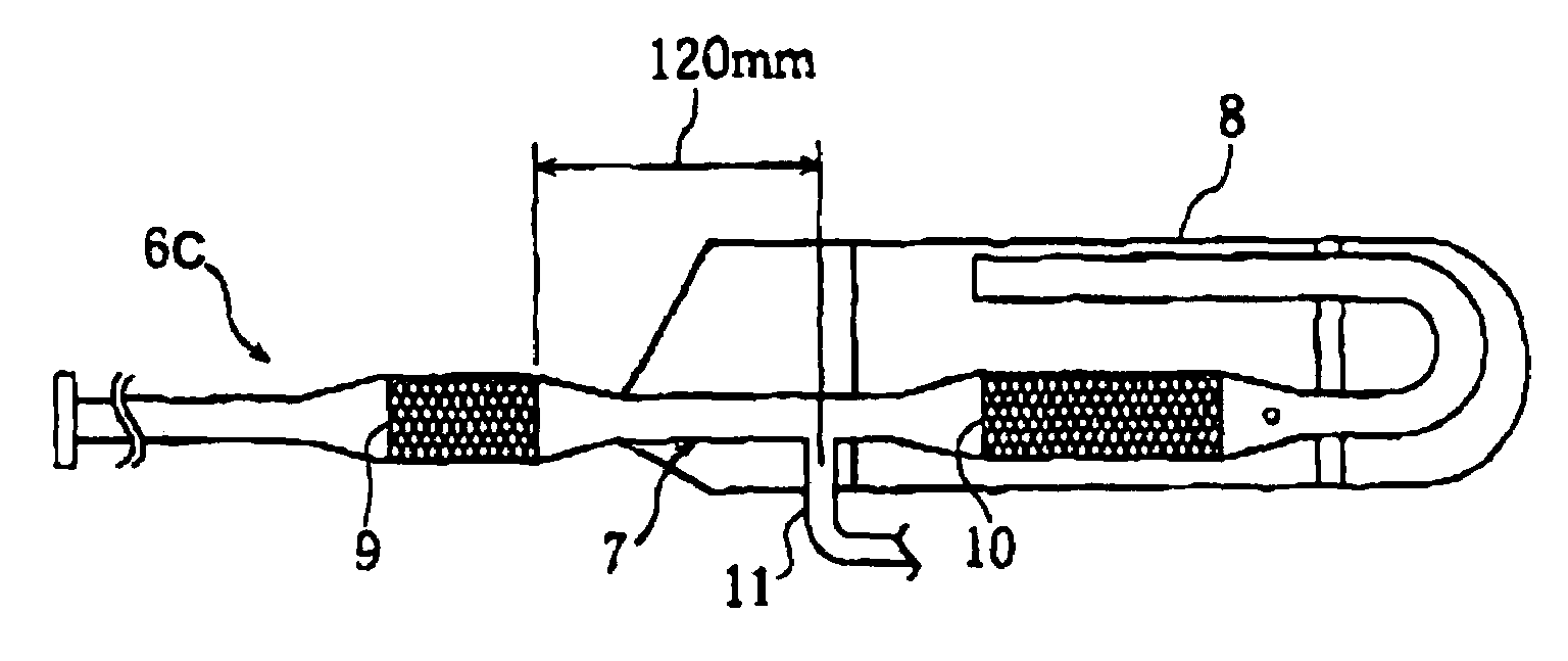
[0034]Embodiments of the present invention will be hereinafter described in connection with the attached drawings.

[0035]With reference to FIG. 6, one embodiment of a four-cycle engine 1 is shown, which engine can be adapted for use in a two wheel motorized vehicle, such as a motorcycle or a scooter, or any other vehicle, such as one that can be driven by a small displacement engine.

[0036]An intake passage 2 is connected to an intake port (not shown) of the engine 1 to conduct a mixture of air and fuel (e.g., combustion gas) to the intake port. A carburetor 3 serving as a fuel supply system is disposed in the intake passage 2 to regulate the mixture of air and fuel. An air cleaner 4 connected to an upstream end of the intake passage 2 filters the air to remove debris and / or contaminants therefrom. This air cleaner 4 has a cleaner case 4a within which an air suction side “a” and an air emission side “b” are defined. An element 5 separates the air suction side “a” form the air emission...


PUM


Abstract

A four-cycle engine is provided that includes an exhaust port for releasing combusted gas from the engine and an exhaust system. The exhaust system includes an exhaust pipe coupled with the exhaust port, a first catalyst, a second catalyst, and a secondary air introduction pipe. The first catalyst is disposed in the exhaust pipe and the second catalyst is disposed in the exhaust pipe a set distance downstream of the first catalyst. The secondary air introduction pipe is configured to introduce air into the exhaust pipe. The secondary air induction pipe is connected to the exhaust pipe between the first and the second catalysts at a location where a temperature difference of the first and the second catalysts in a cold start transient phase is within a predetermined range.

Description

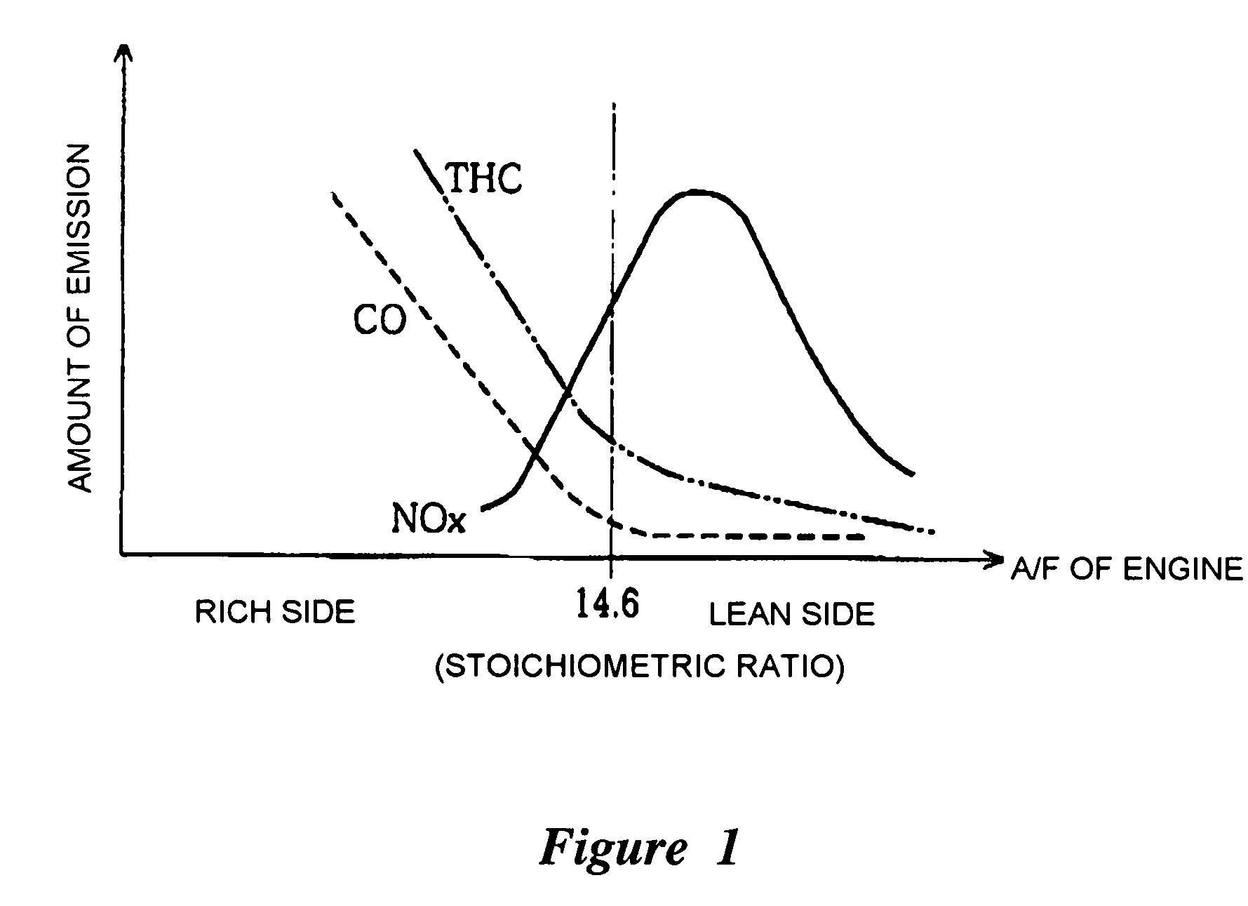
CROSS-REFERENCE TO RELATED APPLICATIONS[0001]This application is a continuation of PCT application PCT / JP2004 / 007924, filed Jun. 7, 2004, which claimed the priority benefit of Japanese Patent Application 2003-174735, filed Jun. 19, 2003 and Japanese Patent Application 2004-084603, filed Mar. 23, 2004, each of which is hereby incorporated by reference in its entirety.BACKGROUND OF THE INVENTION[0002]1. Field of the Invention[0003]This application relates to an exhaust system with an exhaust gas purifier. More particularly, this application relates to a four-cycle engine with such an exhaust system.[0004]2. Description of the Related Art[0005]FIG. 1 shows that the composition of exhaust gas emitted by a four-cycle engine is dependent on the composition of the combustion gas burned by the engine. More particularly, when the air fuel (A / F) ratio varies, the composition of exhaust gas also varies. In this example, as the A / F ratio becomes richer than 14.6, the amount of CO and THC emitte...

Claims


Application Information

Patent Timeline
Patent Type & Authority Patents(United States)
IPC IPC(8): F01N3/00F01N3/22F01N3/24F01N3/30F01N3/34F01N13/02F02B75/02
CPCF01N3/22F01N3/30F01N13/009F02B2075/027Y02T10/20F01N2270/00Y02T10/12
Inventor NISHIMURA, HIDEHIROOOBA, JUNICHITAKII, OSAMU
Owner YAMAHA MOTOR CO LTD
Learn More