Differential scanning calorimeter (DSC) with temperature controlled furnace

a technology of differential scanning calorimeter and furnace, which is applied in the direction of calorimeter, instruments, material thermal analysis, etc., can solve the problems of drift factor in baseline, difficulty in obtaining stability, operating difficulty and lag time between cycles

Active Publication Date: 2008-11-11
PERKINELMER U S LLC
View PDF26 Cites 7 Cited by
  • Summary
  • Abstract
  • Description
  • Claims
  • Application Information

AI Technical Summary

Problems solved by technology

However, as for the baseline performance, there has been a difficulty in obtaining stability.
The main reason of this lies in that the power compensation type sensor has a large temperature difference from surrounding members during measurement with a result that a comparatively large amount of heat leak occurs from the sensor to the outside, causing a drift factor in the baseline.
Moreover, there is operating difficulty and lag time between cycles due to frost formation on the cells during cool down.

Method used


Image

  • Differential scanning calorimeter (DSC) with temperature controlled furnace
  • Differential scanning calorimeter (DSC) with temperature controlled furnace
  • Differential scanning calorimeter (DSC) with temperature controlled furnace

Examples


Embodiment Construction

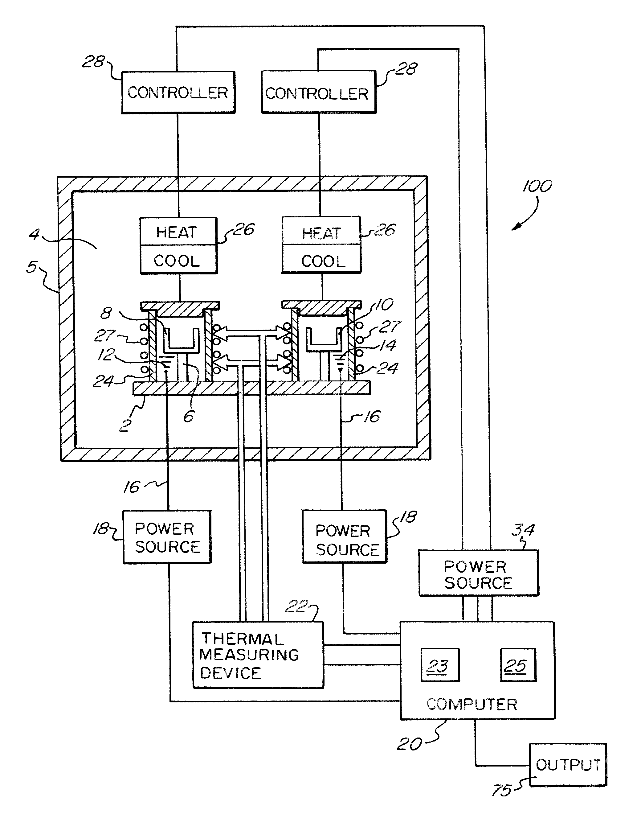
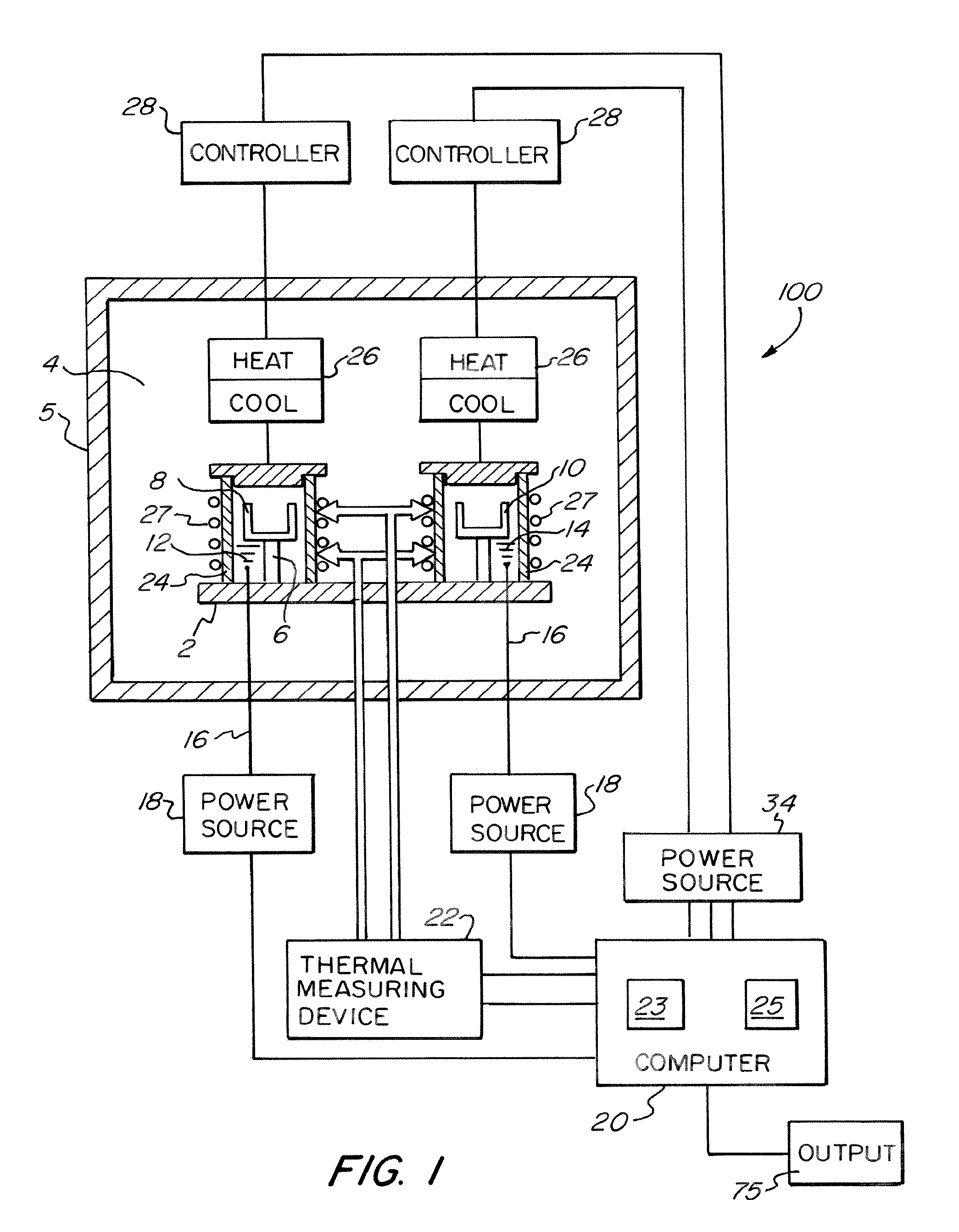
[0018]A schematic diagram of an embodiment of an improved differential scanning calorimeter (DSC) is shown in FIG. 1. A calorimeter 100 such as PerkinElmer's Diamond DSC may be used to incorporate the present teachings; however, other models may be used such as PerkinElmer's power compensated Pyris 1 DSC, PerkinElmer's DSC 7, or the like. The illustrated DSC has a metal base 2 located in an inner chamber 4 defined by an outer wall 5 which may be a heat shield. Metal base 2 may be connected to a cooling block (not shown in FIG. 1). Support 6 on base 2 holds a reference cell 8 and a sample cell 10, each similar in volume and mass, and assembled with heating elements 12 and 14. Reference cell 8 and sample cell 10 each hold a sample in this case (not shown in FIG. 1), however, one of ordinary skill in the art would appreciate that it is possible to leave reference cell 8 empty, and / or that the reference may be data or a sample which may have known characteristics. Leads 16 connect cells...


PUM

PropertyMeasurementUnit
thickaaaaaaaaaa
thickaaaaaaaaaa
temperatureaaaaaaaaaa

Abstract

A differential scanning calorimeter apparatus includes reference and sample cells and controlled temperature shields. The temperature of the shields is controlled such that baseline curvature is reduced by eliminating heat flow from the furnaces to their surroundings (quasi adiabatic conditions) and by controlling heat flow through a well defined solid state heat resistance between the furnaces and a temperature controlled heat sink. The temperature of each shield can be controlled independently to reduce differential heat flow over the whole temperature range of the scan, or maintained at a constant temperature for conventional power compensated DSC operation. The temperature / time profile for each shield can be controlled according to actual furnace temperature, obtained from an empty run, or stored in the computer memory and recalled for sample measurements.

Description

CROSS-REFERENCE TO RELATED APPLICATIONS[0001]This application is a continuation of U.S. patent application Ser. No. 11 / 054,755, filed Feb. 10, 2005 now U.S. Pat. No. 7,371,006, which application is currently pending and which application claims the benefit under 35 U.S.C. §119(e) of the U.S. Provisional Patent Application Ser. No. 60 / 521,036 filed Feb. 10, 2004 herein incorporated by reference.FIELD OF THE INVENTION[0002]This invention relates to calorimetric analytical instruments, and more particularly to a temperature controlled shield for differential scanning calorimeter.BACKGROUND OF THE INVENTION[0003]The differential scanning calorimeter (“DSC”) is an apparatus which, when a sample and a reference substance are placed therein, and the temperatures of both are varied at a constant rate, detects and analyzes differentially a heat flow generated or absorbed by the sample as compared with the reference substance.[0004]As the sample material goes through various physical changes,...

Claims


Application Information

Patent Timeline
Patent Type & Authority Patents(United States)
IPC IPC(8): G01N25/00G01K17/00G01N25/48
CPCG01N25/4866G01K17/00
Inventor SCHICK, CHRISTOPH
Owner PERKINELMER U S LLC
Why Eureka
Try Eureka