Integrated converter having three-phase power factor correction

a technology of integrated converters and power factor corrections, which is applied in the direction of dc network circuit arrangements, dc source parallel operation, energy industry, etc., can solve the problems of high contamination of the power network, high three-phase converter pollution, and high pollution of electronic devices to contaminate the power net, etc., and achieves high utility rate

Active Publication Date: 2008-11-11
DELTA ELECTRONICS INC
View PDF3 Cites 7 Cited by
  • Summary
  • Abstract
  • Description
  • Claims
  • Application Information

AI Technical Summary

Benefits of technology

[0017]In accordance with one aspect of the present invention, an integrated converter having three-phase power factor correction with less elements and a high utility rate is provided. The provided converter is formed by only two power factor correction circuits.

Problems solved by technology

The conventional converter is a nonlinear circuit consisted of the diode or silicon controlled rectifier (SCR), which generates lots of current harmonic waves and zero power and thus becomes the pollution of the electronic device to contaminate the power net.
The power of the three-phase converter is relatively high, so the contamination for the power network is much higher.
The disadvantage of such circuit is that the three-phase input currents will affect each other, and hence the controlling effect of the THD is not good enough.
The disadvantage of the circuit is that the number of elements in such circuit is higher and thus the system power density thereof is lower.
Because the circuit uses too many elements, the production cost therefor is getting higher directly.

Method used


Image

  • Integrated converter having three-phase power factor correction
  • Integrated converter having three-phase power factor correction
  • Integrated converter having three-phase power factor correction

Examples


Embodiment Construction

[0030]The present invention will now be described more specifically with reference to the following embodiment. It is to be noted that the following descriptions of preferred embodiment of this invention are presented herein for purposes of illustration and description only; it is not intended to be exhaustive or to be limited to the precise form disclosed.

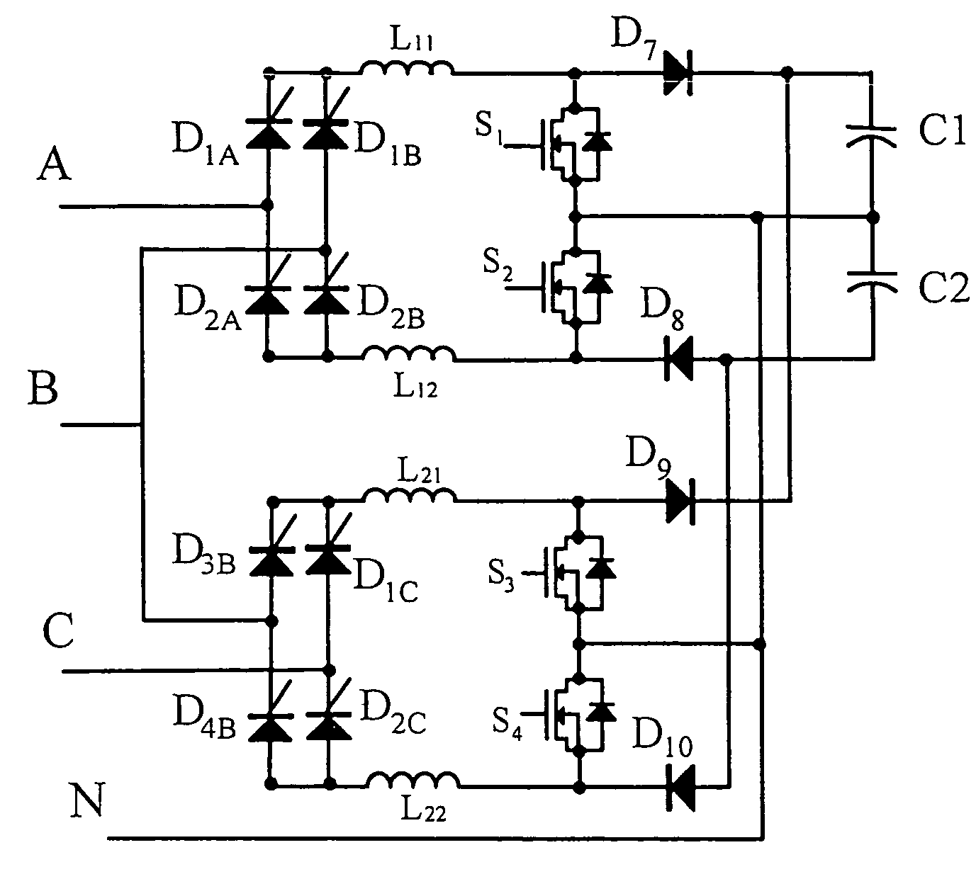
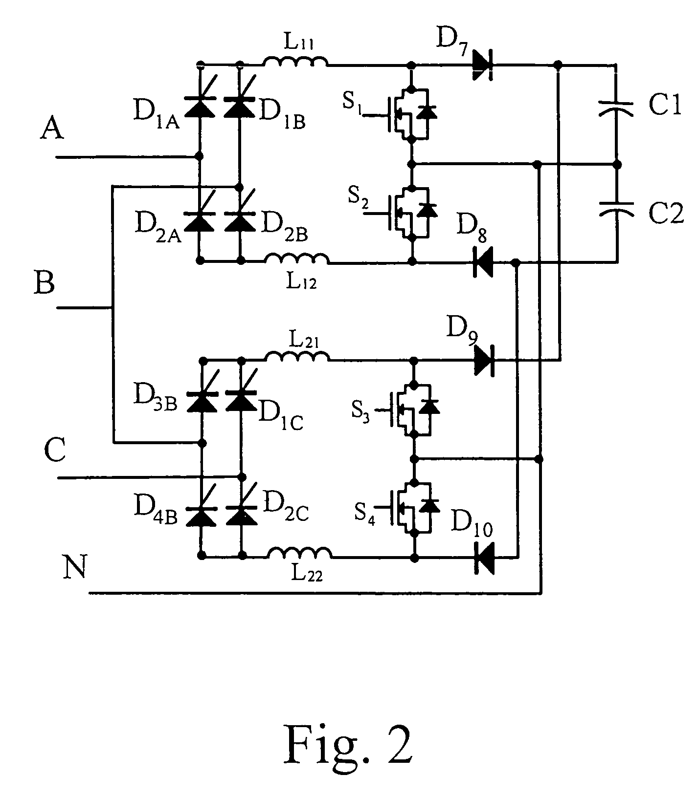
[0031]Please refer to FIG. 2, which shows the circuit diagram of the integrated converter having the three-phase power factor correction according to the first preferred embodiment of the present invention. As shown in FIG. 2, the integrated converter is formed by two power factor correction circuits, the first power factor correction circuit and the second power factor correction circuit. The first power factor correction circuit is formed by a first bridge converter, a first inductance set, and a first DC / DC converter, and the second power factor correction circuit has the same structure as that of the first power factor correct...


PUM


Abstract

An integrated converter having three-phase power factor correction is provided. The integrated converter includes two PFC circuits. Two DC / DC converters are controlled and switched by the integrated converter in accordance with a three-phase AC power source so as to convert the AC power source into a DC power source. The use of the elements in the integrated converter is efficient.

Description

FIELD OF THE INVENTION[0001]The present invention relates to a power inverter, in particular an integrated converter having three-phase power factor correction performed by using semiconductor switches.BACKGROUND OF THE INVENTION[0002]For the past twenty years, the electronic technology has been developed very fast and applied to the fields of the power, the chemical engineer, and the communication. The electronic devices are mostly operated through the converters and the interface of the power net. The conventional converter is a nonlinear circuit consisted of the diode or silicon controlled rectifier (SCR), which generates lots of current harmonic waves and zero power and thus becomes the pollution of the electronic device to contaminate the power net.[0003]The electronic device has been one of the major sources of the harmonic waves. Currently, one of the major methods for inhibiting the harmonic waves produced by the electric device is an active method. The active method designs...

Claims


Application Information

Patent Timeline
Patent Type & Authority Patents(United States)
IPC IPC(8): H02M7/5387
CPCH02M1/4216Y02B70/126Y02B70/10Y02P80/10
Inventor TAN, JING-TAOJIANG, ZHI-QIANGLI, YANGZHU, QUI-HUAYING, JIAN-PINGTSAI, WEN-YIN
Owner DELTA ELECTRONICS INC
Why Eureka
Try Eureka