
Microfluidic particle-analysis systems

a microfluidic particle and analysis system technology, applied in the field of microfluidic particle analysis systems for the manipulation and/or detection of particles, can solve the problems of small assay volume in high-density microtiter plates, a number of shortcomings, and the need for new approaches

Inactive Publication Date: 2008-11-18
FLUIDIGM CORP
View PDF247 Cites 102 Cited by
  • Summary
  • Abstract
  • Description
  • Claims
  • Application Information

AI Technical Summary

Problems solved by technology

As the number of possible combinations of samples, reagents, and assays becomes nearly incalculable, it has become increasingly apparent that novel approaches are necessary even to begin to make sense of this complexity, especially within reasonable temporal and monetary limitations.
However, very small assay volumes in high-density microtiter plates, particularly assays with cells, may suffer from a number of shortcomings.
For example, cells may be lost easily from wells, may be harmed by rapid fluid evaporation, may contaminate nearby wells, and may be difficult to remove efficiently from wells for additional analysis or culture.

Method used


Image

  • Microfluidic particle-analysis systems
  • Microfluidic particle-analysis systems
  • Microfluidic particle-analysis systems

Examples


example 1

Cell Positioning and Retention Mechanisms

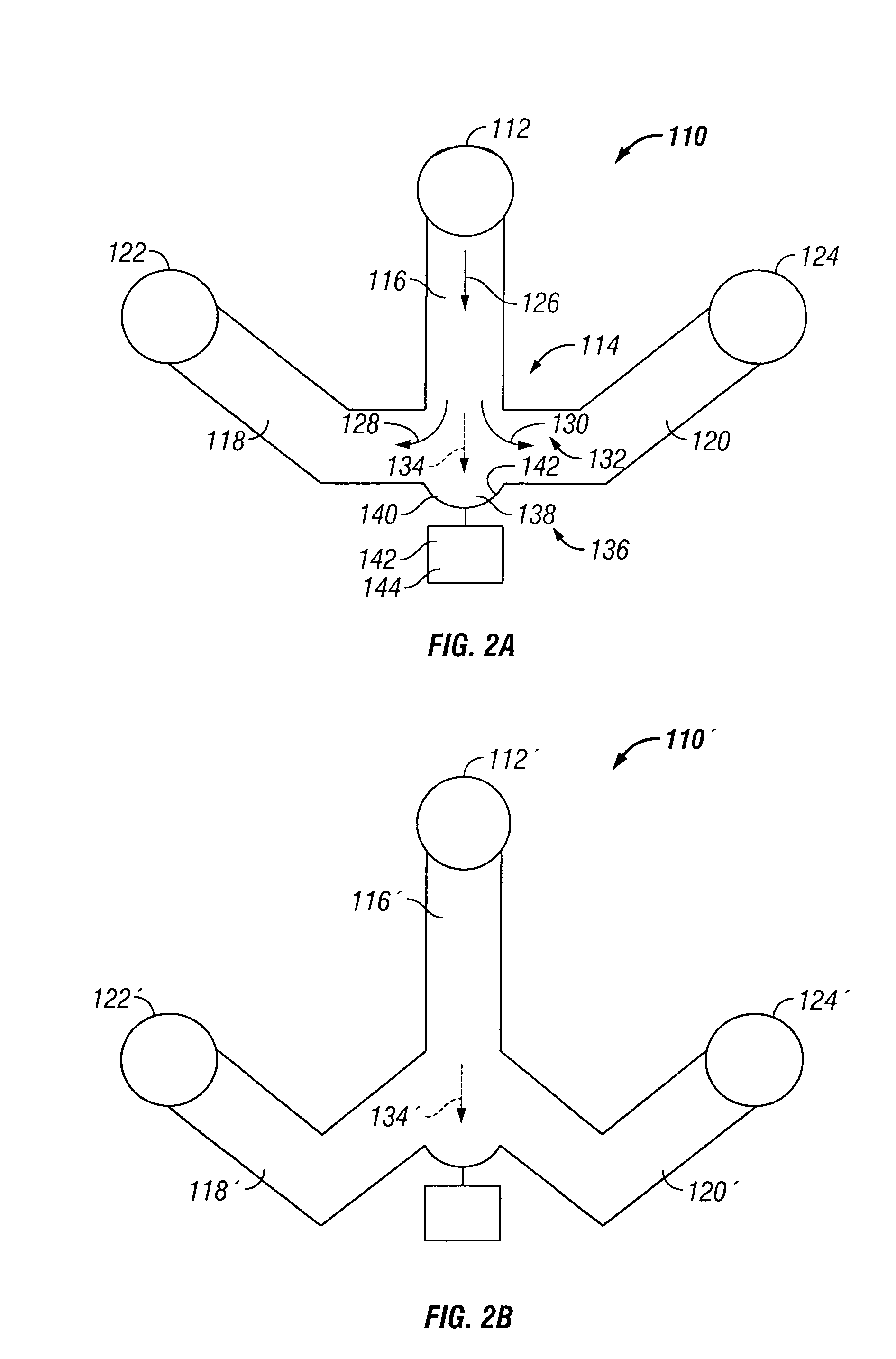
[0335]This example describes microfluidic systems for positioning and / or retaining single particles or groups of particles, based, at least in part, on divergent flow paths; see FIGS. 2-4.

[0336]Background

[0337]There are many cell analyses that benefit from or require the precise positioning and retention of a single cell or a small group of cells. In particular, positioned and retained cells may be treated and observed in real time. However, currently available mechanisms for positioning and retaining cells are either expensive and labor intensive, or imprecise and deleterious to cells. For example, micromanipulators enable a user to select and precisely position a single cell. However, micromanipulators are expensive, and require that users observe the cell throughout the micromanipulation. Hence, the user can only position one cell at a time. At the other extreme, filters offer a crude, but much cheaper and faster mechanism for positioning ...

example 2

Microfluidic Systems for Trapping and Perfusing Particles

[0348]This example describes microfluidic systems that position and retain single particles or sets of particles, and allow rapid, precise perfusion of the retained particles or sets of particles with reagents; see FIGS. 5-11C.

[0349]Background

[0350]Many cell studies benefit from analysis of a population of cells. The population may provide discrete information from individual cells of the population and averaged information from the entire population. Accordingly, a population of cells may allow concurrent analysis of distinct types of cells when the population is heterogeneous, or a range of cell phenotypes or responses when the population is homogeneous or clonal. Therefore, studies of cells in a microfluidic environment would benefit from microfluidic systems that automatically position and / or retain a set of cells at a preselected site on a microfluidic chip. Furthermore, these studies would benefit from mechanisms that al...

example 3

Microfluidic Systems for Parallel Retention and / or Treatment of

[0388]Particles

[0389]This example describes microfluidic mechanisms and systems that position a plurality of particles and / or reagents at discrete transverse regions and flow paths within a channel or flow stream; see FIGS. 12-13K. This positioning may allow parallel retention of distinct particles at adjacent, but distinct, sites and / or parallel exposure of particles at these sites to distinct reagents.

[0390]Background

[0391]Biological analyses benefit from a capability to directly compare the phenotypes of two or more cells or groups of cells, under similar or distinct treatment regimens. However, in the macroscopic world, such cells or group of cells often are treated at distinct, relatively widely spaced sites, such as different tissue culture dishes or wells of a microtiter plate, potentially exposing the cells to undesired differences in treatment conditions. Accordingly, such analyses may need to be averaged over m...


PUM

PropertyMeasurementUnit
volumesaaaaaaaaaa
volumesaaaaaaaaaa
volumesaaaaaaaaaa

Abstract

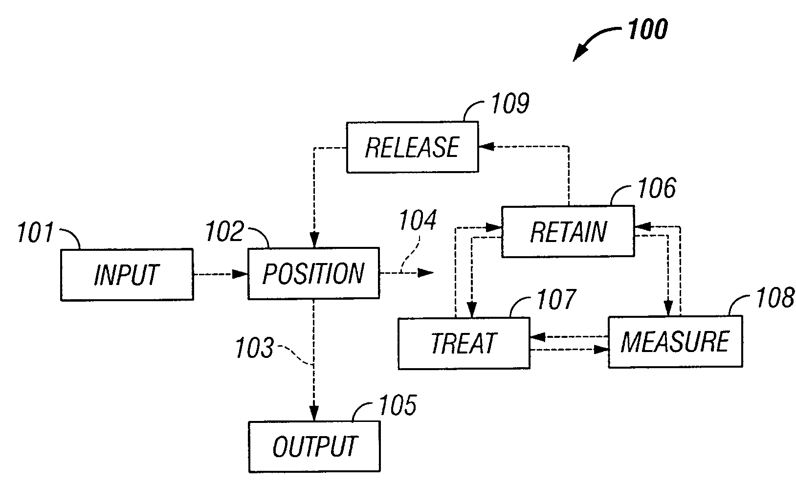
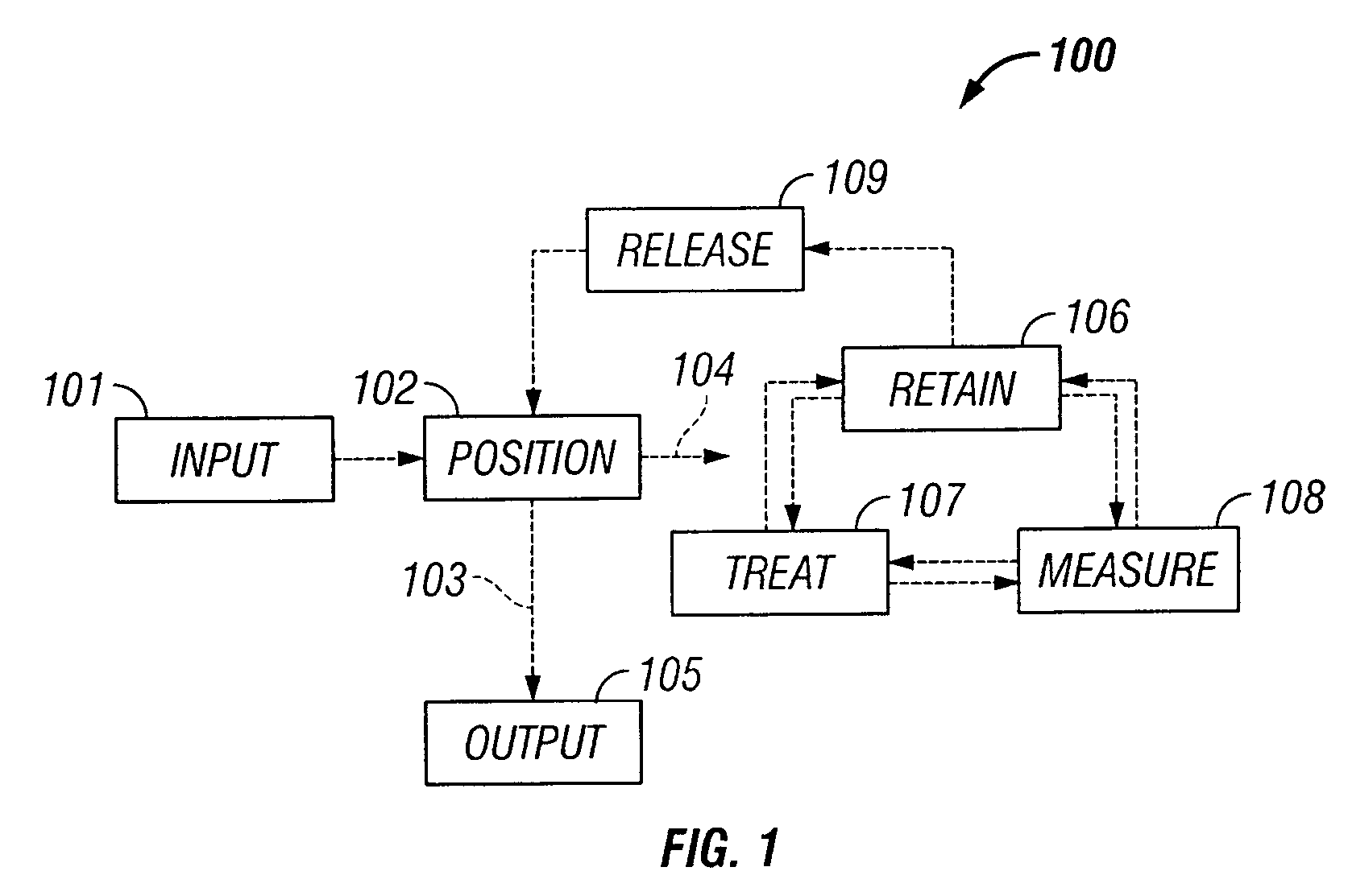
The invention provides systems, including apparatus, methods, and kits, for the microfluidic manipulation and / or detection of particles, such as cells and / or beads. The invention provides systems, including apparatus, methods, and kits, for the microfluidic manipulation and / or analysis of particles, such as cells, viruses, organelles, beads, and / or vesicles. The invention also provides microfluidic mechanisms for carrying out these manipulations and analyses. These mechanisms may enable controlled input, movement / positioning, retention / localization, treatment, measurement, release, and / or output of particles. Furthermore, these mechanisms may be combined in any suitable order and / or employed for any suitable number of times within a system. Accordingly, these combinations may allow particles to be sorted, cultured, mixed, treated, and / or assayed, among others, as single particles, mixed groups of particles, arrays of particles, heterogeneous particle sets, and / or homogeneous particle sets, among others, in series and / or in parallel. In addition, these combinations may enable microfluidic systems to be reused. Furthermore, these combinations may allow the response of particles to treatment to be measured on a shorter time scale than was previously possible. Therefore, systems of the invention may allow a broad range of cell and particle assays, such as drug screens, cell characterizations, research studies, and / or clinical analyses, among others, to be scaled down to microfluidic size. Such scaled-down assays may use less sample and reagent, may be less labor intensive, and / or may be more informative than comparable macrofluidic assays.

Description

CLAIM OF PRIORITY[0001]This application is a divisional of U.S. patent application Ser. No. 10 / 405,953, entitled “MICROFLUIDIC PARTICLE-ANALYSIS SYSTEMS,” filed Apr. 1, 2003 now U.S. Pat. No. 7,312,085 by Hou-Pu Chou et al. (“the '953 application)”, the entire disclosure of which is incorporated herein by reference for all purposes. The '953 application claims the benefit of priority under 35 U.S.C. §119(e) to provisional applications Ser. No. 60 / 369,538, filed Apr. 1, 2002 and Ser. No. 60 / 378,464, filed May 6, 2002, both of which are hereby incorporated by reference in their entirety for all purposes and those purposes stated herein and therein. This application further claims priority under 35 U.S.C. §120 as a continuation-in-part of the non-provisional patent application No. 10 / 405,092, titled “Microfluidic Particle-Analysis Systems”, by Chou et al., filed on Mar. 31, 2003, which is hereby incorporated by reference for all purposes.CROSS-REFERENCES TO PATENT APPLICATIONS[0002]Thi...

Claims


Application Information

Patent Timeline
Patent Type & Authority Patents(United States)
IPC IPC(8): G01N35/00G01N1/10G01N15/06G01N33/00G01N33/48B01L3/00G01N15/02G01N15/14
CPCB01L3/502761G01N15/1456G01N15/1468G01N15/1484B01L3/502746Y10T436/2575B01L2200/0636B01L2200/0647B01L2200/0652B01L2200/0668B01L2200/10B01L2200/12B01L2300/0645B01L2300/0681B01L2300/0861B01L2300/0867B01L2300/087B01L2300/0887B01L2300/123B01L2400/0409B01L2400/0481B01L2400/0655G01N2015/0288G01N2015/1075G01N2015/149G01N2015/1493Y10T436/11B01L3/502753G01N35/00
Inventor CHOU, HOU-PUDARIDON, ANTOINEFARRELL, KEVINFOWLER, BRIANLIAU, YISH-HANNMANGER, IAN D.NASSEF, HANY RAMEZTHRONDSET, WILLIAM
Owner FLUIDIGM CORP
Learn More