Multilayer coil component

a coil and multi-layer technology, applied in the direction of transformer/inductance details, printed inductances, inductances, etc., can solve the problems of disadvantageous increase of coil conductor types and difficulty in fine adjustment of inductan

Active Publication Date: 2008-11-18
MURATA MFG CO LTD
View PDF9 Cites 30 Cited by
  • Summary
  • Abstract
  • Description
  • Claims
  • Application Information

AI Technical Summary

Benefits of technology

[0007]In order to overcome the problems described above, preferred embodiments of the present invention provide a multilayer coil component in which inductance can be finely adjusted and the coupling between two helical coils can be strengthened without increasing the types of patterns of coil conductors.
[0009]In the multilayer coil component according to a preferred embodiment of the present invention, the first and second helical coils are coaxially positioned and are connected to each other in parallel, and thus, a withstand current value is large. Since the first and second helical coils have different numbers of turns, inductance can be finely adjusted by individually changing the number of turns. Furthermore, since the sum of turns of the coil conductors facing each other of the first and second helical coils at a portion where the first and second coil units are adjacent to each other is larger than the sum of turns of the coil conductors positioned on both outer sides in the coil axis direction of the first and second helical coils, the coupling between the two helical coils is strengthened and inductance increases. In addition, since the input leading electrode of any one of the helical coils and the output leading electrode of the other helical coil are adjacent to each other in the laminated direction, the types of patterns of the coil conductors does not increase regardless of the strong coupling between the coils.
[0010]In the multilayer coil component according to various preferred embodiments of the present invention, it is preferable that an input leading electrode of either one of the first and second helical coils and an output leading electrode of the other helical coil are led to end surfaces opposite to each other of the laminated body. With this configuration, external electrodes can be formed over the end surfaces of the laminated body, so that manufacturing can be easily performed.
[0011]Preferably, input leading electrodes or output leading electrodes of the first and second helical coils have the same pattern. By using the same pattern, the manufacturing process is simplified.
[0012]When each of the coil conductors in a main portion of the first and second helical coils has a substantially ¾-turn shape, the number of laminated layers of the coil conductors reduces and the component can be miniaturized. Preferably, in a plan view in the laminated direction, the plurality of coil conductors are substantially rectangular, the via-hole conductors are located at two points in each of long sides of the substantially rectangular shape, and the via-hole conductors are not placed on the same straight line in the short side direction of the substantially rectangular shape. Accordingly, the via-hole conductors are isolated from each other and a short circuit can be prevented.
[0013]According to various preferred embodiments of the present invention, a withstand current value is large, inductance can be finely adjusted, the coupling between the first and second helical coils can be strengthened, inductance can be increased, and the number of types of patterns of necessary coil conductors is small.

Problems solved by technology

This causes a significant change in inductance and a problem that fine adjustment of inductance is difficult.
That is, the positions of the via-hole conductors 75 are different in the same patterns of coil conductors, and thus, the types of patterns of the coil conductors increase disadvantageously.

Method used


Image

  • Multilayer coil component
  • Multilayer coil component
  • Multilayer coil component

Examples


first preferred embodiment

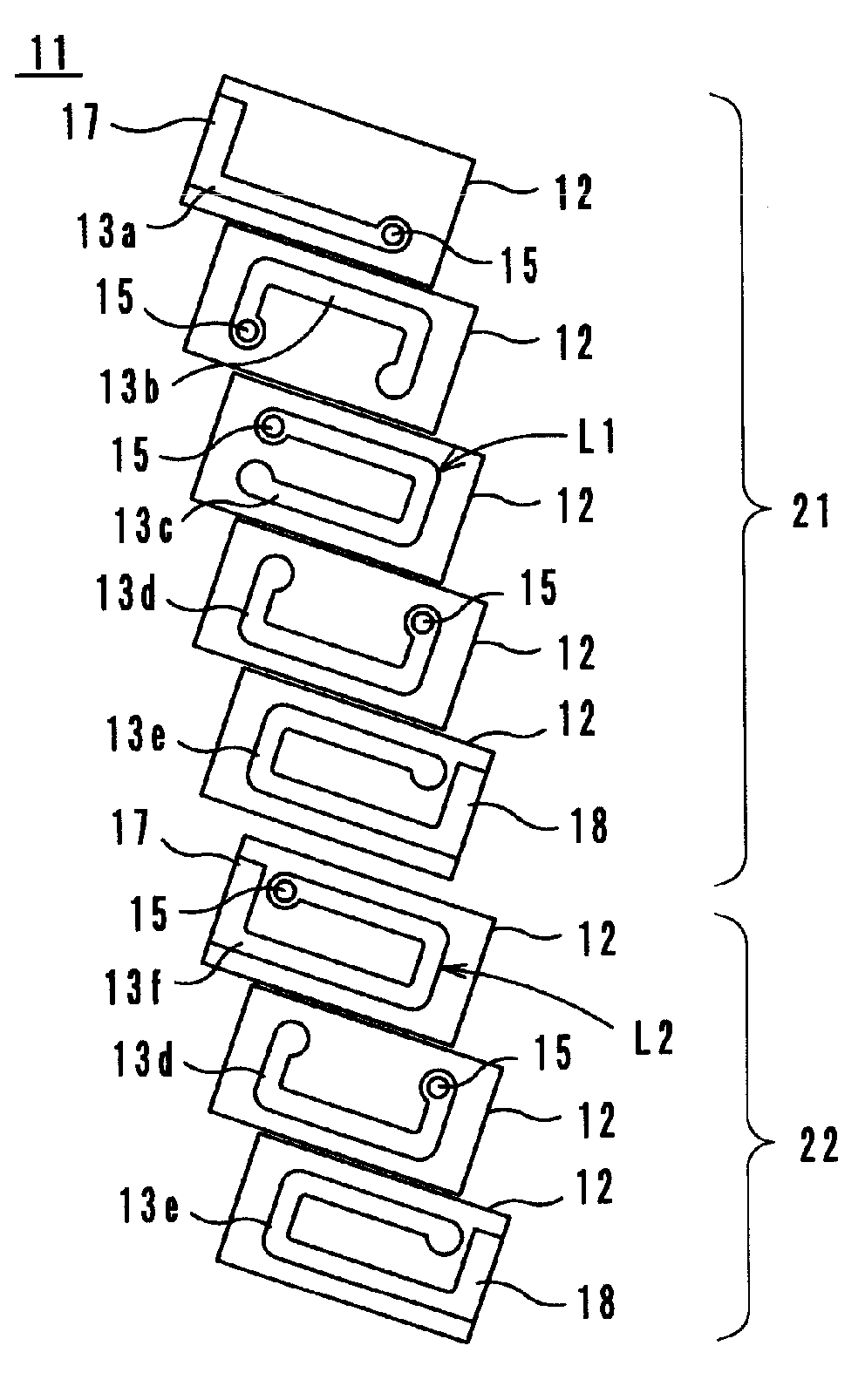
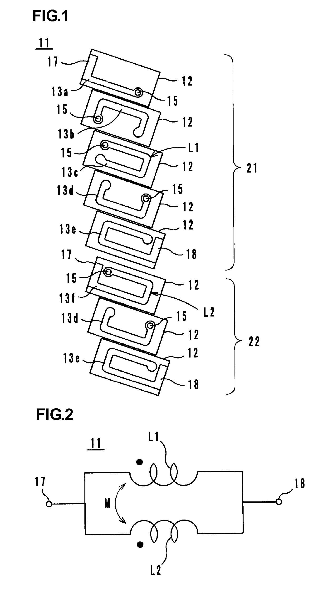
[0025]As shown in FIG. 1, a multilayer coil component 11 according to a first preferred embodiment has the following configuration. A first coil unit 21 including laminated ceramic green sheets 12 provided with coil conductors 13a to 13e and via-hole conductors 15 is stacked on a second coil unit 22 including laminated ceramic green sheets 12 provided with coil conductors 13f, 13d, and 13e and via-hole conductors 15, and protective ceramic green sheets (not shown) are further laminated at the top and bottom.

[0026]The ceramic green sheets 12 are preferably fabricated in the following way. First, materials including ferrite powder, a bonding agent, and a plasticizing agent are mixed and crushed by a ball mill into a slurry composition, and vacuum defoaming is performed thereon. The obtained result is formed into sheets each having a predetermined thickness by a doctor blade method or the like.

[0027]Next, a hole serving as a via-hole is formed by laser irradiation at a predetermined po...

second preferred embodiment

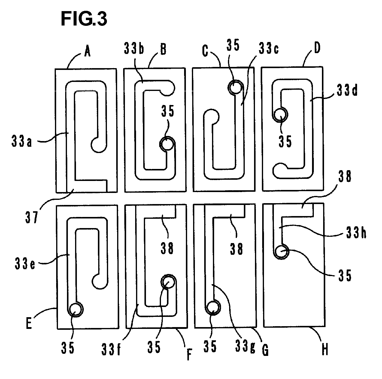
[0036]In the second preferred embodiment, various multilayer coil components are fabricated by using, for example, eight types of sheets A to H shown in FIG. 3. In the sheets A to H, coil conductors 33a to 33h, an input leading electrode 37, output leading electrodes 38, and via-hole conductors 35 are provided on ceramic green sheets. As described below in detail, the respective via-hole conductors 35 are arranged in an offset state. Accordingly, spaces between the via-hole conductors 35 become wide and a short circuit can be prevented.

[0037]FIG. 4A illustrates a multilayer coil component 40a including a first coil unit 41 including a helical coil L1 and a second coil unit 42 including a helical coil L2. For comparison, FIG. 4B illustrates a multilayer coil component 40b in which the laminated positions of the first and second coil units 41 and 42 are interchanged.

[0038]FIG. 5A illustrates a multilayer coil component 45a including a first coil unit 46 including a helical coil L1 and...


PUM

PropertyMeasurementUnit
currentaaaaaaaaaa
inductanceaaaaaaaaaa
currentaaaaaaaaaa

Abstract

A multilayer coil component is constructed such that inductance can be finely adjusted and the coupling between two helical coils can be strengthened without increasing the types of patterns of coil conductors. Coil conductors of a first coil unit are connected to each other in series via via-hole conductors so as to form a first helical coil. Coil conductors of a second coil unit are connected to each other in series via via-hole conductors so as to form a second helical coil. The first and second helical coils are coaxially positioned, have different numbers of turns, and are electrically connected to each other in parallel. The sum of turns of the coil conductors facing each other at a portion where the first coil unit and the second coil unit are adjacent to each other is larger than the sum of turns of the coil conductors positioned on both outer sides in the coil axis direction of the first and second helical coils.

Description

BACKGROUND OF THE INVENTION[0001]1. Field of the Invention[0002]The present invention relates to multilayer coil components, particularly to a multilayer coil component including two helical coils electrically connected to each other in parallel and laminated in a laminated body.[0003]2. Description of the Related Art[0004]Conventionally, a multilayer coil component described in Japanese Unexamined Patent Application Publication No. 6-196334 has been known. As shown in FIG. 8, the multilayer coil component 71 has a configuration in which a first coil unit 78 is stacked on a second coil unit 79, each coil unit including laminated ceramic sheets 72 provided with coil conductors 73a to 73e and via-hole conductors 75. The coil conductors 73a to 73e are mutually connected in series via the via-hole conductors 75 so as to form helical coils 73A and 73B. The two helical coils 73A and 73B are electrically connected to each other in parallel so as to form a multilayer coil component having a...

Claims


Application Information

Patent Timeline
Patent Type & Authority Patents(United States)
IPC IPC(8): H01F5/00
CPCH01F17/0013H01F2017/002H01F2027/2809H01F2005/006
Inventor MAEDA, TOMOYUKIUEDA, MITSURU
Owner MURATA MFG CO LTD
Why Eureka
Try Eureka