
Electronic equipment provided with cooling system

a technology of electronic equipment and cooling system, which is applied in the direction of domestic cooling equipment, lighting and heating equipment, instruments, etc., can solve the problems of shortening the life of the fan, increasing so as to reduce the noise, increase the noise in the system, and reduce the effect of nois

Active Publication Date: 2008-11-25
MAXELL HLDG LTD
View PDF9 Cites 52 Cited by
  • Summary
  • Abstract
  • Description
  • Claims
  • Application Information

AI Technical Summary

Benefits of technology

The invention is a control method for a fan and pump in an electronic equipment with a liquid-cooling system and a fan air-cooling system as a cooling system. The method aims to efficiently use the liquid-cooling system, suppress an increase in noise caused by the fan, and prolong the life of the fan and pump. The control device determines and controls the voltages of the pump and fan based on the temperature detected by a temperature sensor and pre-defined storage information. The method also takes into account the viscosity of the liquid circulating in the system and avoids excessive operations of both the fan and pump. The technical effects of the invention include reducing noise, improving cooling efficiency, and prolonging the life of the cooling system components.

Problems solved by technology

Since the hybrid cooling system uses a fan, noise in the system is increased.
Also, in the case where a fan and a pump for driving of a liquid are not balanced well in capacity, the fan is in some cases unnecessarily operated even when cooling can be achieved by increasing a fluid flow rate with the use of a pump, and such operation of the fan incurs an increase in noise and shortening of life of the fan in some cases.

Method used


Image

  • Electronic equipment provided with cooling system
  • Electronic equipment provided with cooling system
  • Electronic equipment provided with cooling system

Examples


Embodiment Construction

[0026]An electronic equipment provided with a cooling system according to an embodiment of the invention will be described below in detail with reference to FIGS. 1 to 8. The embodiment will be described taking as an example the case where a cooling system is applied to a desktop type personal computer (referred below to as desktop PC).

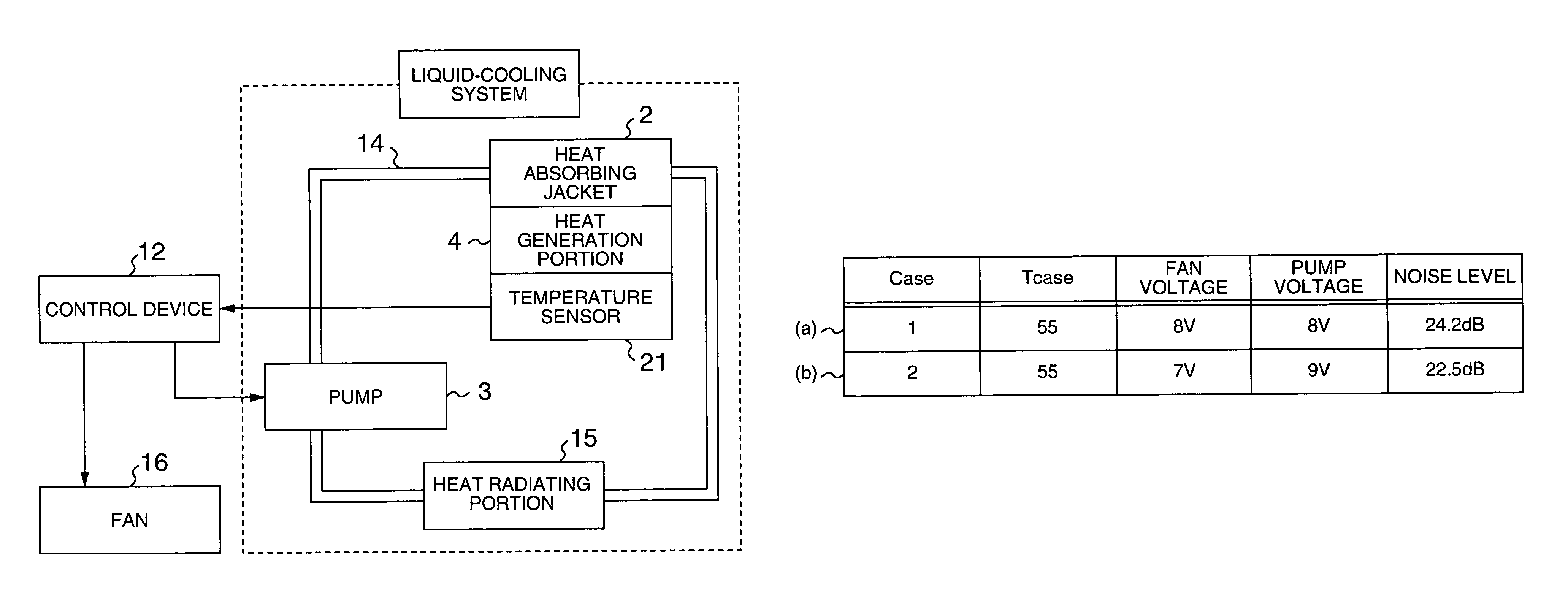
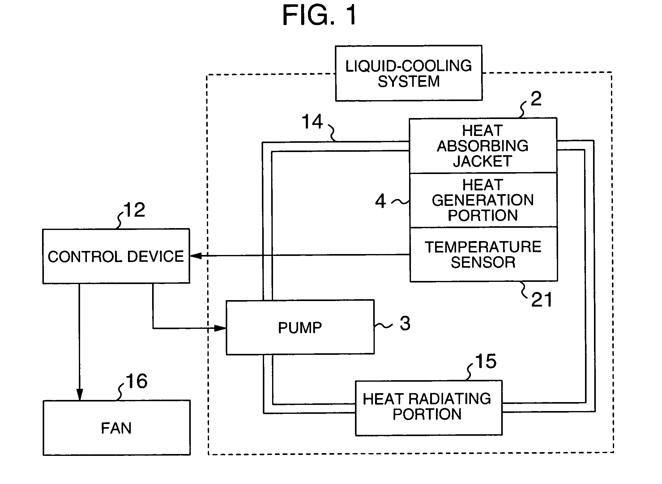
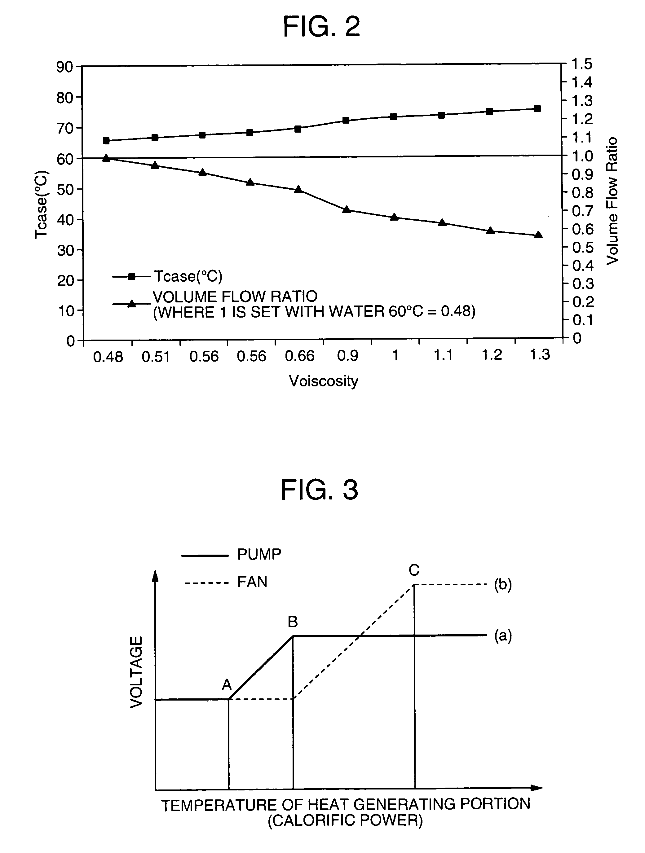
[0027]Here, FIG. 1 is a block diagram showing a construction of a cooling system, according to the embodiment of the invention, provided with a liquid-cooling system and a fan air-cooling system. FIG. 2 is a graph showing a viscosity characteristic of a circulating liquid used in the cooling system according to the embodiment of the invention. FIG. 3 is a graph showing the relationship between temperature of a heat generating portion and voltages of a pump and a fan, the relationship being stored in a control device in the embodiment of the invention. FIG. 4 is a view showing examples of control values of a fan voltage and a pump voltage at a certain ...


PUM


Abstract

An electronic equipment is provided, which comprises a liquid-cooling system and a cooling fan as a cooling system, efficiently cools the liquid-cooling system, and reduces fan noise. The electronic equipment is provided with a liquid-cooling system, in which heat generated in a heat generating portion is transmitted to a heat radiating portion with a liquid as a medium to achieve cooling, and an air-cooling system, in which heat transmitted to the heat radiating portion is forcedly cooled, and comprises a pump that circulates the liquid between the heat generating portion and the heat radiating portion, a fan that forcedly discharges heat of the heat radiating portion to an outside, a temperature sensor that detects temperature of the heat generating portion, and storage information that beforehand prescribes the relationship between temperature of the heat generating portion and voltages of the pump and the fan, the electronic equipment being constructed such that a pump voltage is raised without changing a fan voltage when the detected temperature exceeds a first temperature, and a fan voltage is raised when temperature detected by the temperature sensor exceeds a second temperature higher than the first temperature, thus further increasing a cooling capacity.

Description

CROSS-REFERENCE TO RELATED APPLICATION[0001]The present application claims priority from JP-A-2003-291511, the entirety of which is hereby incorporated by reference.BACKGROUND OF THE INVENTION[0002]1. Field of the Invention[0003]The present invention relates to a cooling system for an electronic equipment, the cooling system comprising a liquid-cooling system that cools a heat generating portion with a liquid as a medium, and a forced air-cooling system that uses a fan to discharge heat transported from the heat generating portion to an outside.[0004]2. Description of the Related Art[0005]It is a well-known fact that semiconductors used in an electronic equipment, especially, semiconductors typified by CPU in an information processing equipment have developed amazingly, and have steadily followed a tendency toward an increase in calorific power and density. Correspondingly, a cooling system has also developed steadily as in a natural air-cooling system, in which heat is transmitted ...

Claims


Application Information

Patent Timeline
Patent Type & Authority Patents(United States)
IPC IPC(8): F25D9/00F28D20/02F25D1/00F28D15/02G06F1/20H01L23/34H01L23/467H01L23/473H05K7/20
CPCG06F1/206H05K7/20281F16L55/00
Inventor SATO, KATSUYAOIKAWA, HIRONORI
Owner MAXELL HLDG LTD
Learn More