Method for improving the imaging properties of a projection objective for a microlithographic projection exposure apparatus

a technology of exposure apparatus and imaging properties, which is applied in the field of improving the imaging properties of projection objective for microlithographic exposure apparatus, can solve the problem that deviations cannot actually have a perturbing effect on imaging, and achieve the effect of improving the imaging properties of projection objective and high accuracy

Active Publication Date: 2008-11-25
CARL ZEISS SMT GMBH
View PDF12 Cites 3 Cited by
  • Summary
  • Abstract
  • Description
  • Claims
  • Application Information

AI Technical Summary

Benefits of technology

[0014]It is therefore an object of the invention to provide a method for improving the imaging properties of a projection objective for a microlithographic projection exposure apparatus so that even very small structures can be imaged with a high accuracy on the photosensitive layer.
[0024]The actual value of the imaging quantity may be determined either by means of a measurement or by means of a simulation. A measurement has the advantage that unknown perturbations which degrade the imaging quality can be considered as well. In cases when the actual value can be measured only with difficulty, however, a simulation may be more expedient. A simulation should also be performed when the method is being carried out not in the context of correcting an existing projection objective, but in the context of designing a projection objective which has yet to be produced. Use of the method as a design tool has the advantage that there are then substantially more available corrective measures which can be used to make the actual value of the imaging quantity approximate the desired value for the at least one image point. For example, this may also involve the selection of the optical materials used.
[0026]In this context, however, it is particularly advantageous to use a shearing interferometer for this measurement. In such an measurement, a diffraction grating is arranged in the image plane of the projection objective, and an interference pattern generated by the grating is detected in an electronic image detector. Such wavefront detectors permit wavefront determination virtually in real-time so that the method according to the invention may, for example, be used when the projection operation has to be interrupted, for instance because the masks need to be replaced. Rapid determination of the wavefront in the image plane with the aid of such wavefront detectors even makes it possible to carry out steps c) to e) in an exposure pause between two exposures. In this way, it is also possible to correct those imaging errors which do not occur until during projection operation of the apparatus. These may, for example, be due to changes of the temperature distribution in the optical elements, as already mentioned above.
[0031]To this end, the prior art discloses manipulators which make it possible for the relevant optical element or even the mask to be translated in the X, Y and / or Z direction, rotated and tilted or bent.
[0035]After the corrective measures previously determined by calculation have been implemented according to step e), it may be advantageous to carry out a control measurement by determining again the value of the imaging property, e.g. the actual wavefront profile, according to step c). In this way, it is possible to verify whether the implemented corrective measures do indeed lead to the intended improvement of the imaging of the mask onto the photosensitive layer.
[0039]By corrective measures to be implemented after the apparatus has been put into operation, or even by suitable measures in the context of designing the projection objective, the invention now makes it possible to achieve a significant improvement of the polarization properties. Here again, what is crucial is that only the regions actually illuminated in the exit pupil are considered when these measures are determined.

Problems solved by technology

However, if these locations are not in fact illuminated with a given mask and a given illumination angle distribution, then these deviations cannot actually have a perturbing effect on the imaging.

Method used


Image

  • Method for improving the imaging properties of a projection objective for a microlithographic projection exposure apparatus
  • Method for improving the imaging properties of a projection objective for a microlithographic projection exposure apparatus
  • Method for improving the imaging properties of a projection objective for a microlithographic projection exposure apparatus

Examples


Embodiment Construction

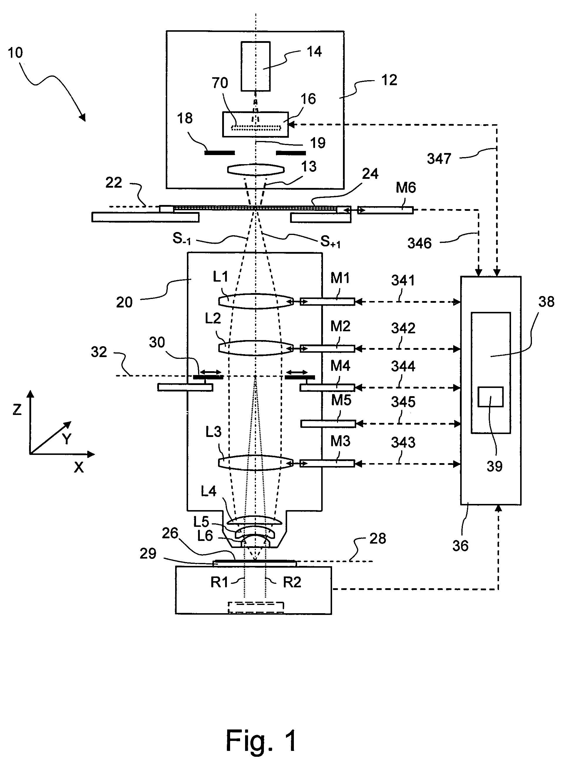
[0059]FIG. 1 shows a meridian section through a microlithographic projection exposure apparatus, denoted overall by 10, in a highly schematized representation which is not true to scale. The projection exposure apparatus 10 has an illumination system 12 for generating projection light 13, which comprises a light source 14, illumination optics indicated by 16 and a diaphragm 18. The illumination optics 16 make it possible to set different illumination angle distributions. To this end, for example, the illumination system may contain interchangeable diffractive optical elements or microlens arrays. Besides this, the illumination optics 16 may also contain axicon elements, lenses or prisms which are arranged so that they can be displaced along the optical axis 19. Since such illumination optics are known in the prior art, see for example U.S. Pat. No. 6,285,443 A, further details of these will not be explained.

[0060]The projection exposure apparatus 10 also has a projection objective 2...


PUM


Abstract

In a method for improving the imaging properties of a projection objective of a microlithographic projection exposure apparatus, an appropriate illumination angle distribution adapted to a mask (24; 224) to be projected is selected. Then locations (40a, 40b; 60a, 60b; 80a, 80b, 80c) in an exit pupil of the projection objective (20), which are illuminated under these conditions by projection light during a projection of the mask, are determined. For at least one image point, an actual value of an imaging quantity, e.g. a wavefront profile or a polarization state, is determined that influences the imaging properties of the projection objective. Finally, corrective measures are calculated such that the actual value of the imaging quantity approximates a desired value at these locations. In this last step, however, deviations of the actual value from the desired value are taken into account exclusively at said locations illuminated in the exit pupil.

Description

BACKGROUND OF THE INVENTION[0001]1. Field of the Invention[0002]The invention relates to a method for improving the imaging properties of a projection objective for a microlithographic projection exposure apparatus. In particular, the invention relates to a method in which various quantities, which have an effect on the imaging properties of the projection objective, are determined in an exit pupil of the projection objective.[0003]2. Description of the Prior Art[0004]For the production of large-scale integrated electrical circuits and other microstructured components, a plurality of structured layers is applied on a suitable substrate which may be, for example, a silicon wafer. In order to structure the layers, they are first covered with a photoresist which is sensitive to light of a particular wavelength range, for example light in the deep ultraviolet (DUV) spectral range. The wafer coated in this way is subsequently exposed in a projection exposure apparatus. During the exposur...

Claims


Application Information

Patent Timeline
Patent Type & Authority Patents(United States)
IPC IPC(8): G03B27/54G03B27/72
CPCG03F7/701G03F7/70566G03F7/70591G03F7/706
Inventor WEGMANN, ULRICHKAMENOV, VLADIMIRMUELDERS, THOMASGRUNER, TORALFMENGEL, MARKUS
Owner CARL ZEISS SMT GMBH
Why Eureka
Try Eureka