Methods and systems for laser calibration and eye tracker camera alignment

a laser calibration and eye tracking technology, applied in the field of laser calibration and can solve problems such as laser system faults, achieve the effects of facilitating eye tracking camera alignment, increasing the overall system cost and complexity, and enhancing calibration accuracy

Inactive Publication Date: 2008-11-25
AMO MFG USA INC
View PDF17 Cites 12 Cited by
  • Summary
  • Abstract
  • Description
  • Claims
  • Application Information

AI Technical Summary

Benefits of technology

[0008]The present invention provides methods, systems, and apparatus for calibrating a laser ablation system, such as an excimer laser system for selectively ablating a cornea of a patient's eye. The invention also facilitates alignment of eye tracking cameras (which are often used in conjunction with such laser systems) that measure a position of the eye during laser eye surgery. In particular, the present invention provides methods and systems which measure laser energy, laser beam shape, and / or laser beam dimensions with enhanced calibration accuracy without significantly increasing the overall system cost and complexity. Moreover, the present invention allows for laser calibrations and eye tracker camera alignment to be effectively and conveniently carried out.
[0012]As described above, the surface preferably comprises a mirror having a reflecting surface, wherein a photodetector measures sample energy, such as laser energy leakage through the mirror. The feature comprises an opening in the calibration fixture which is positioned adjacent a treatment plane, wherein a photodetector measures laser light energy passing through the opening. A variation in each photodetector due to spatial non-uniformity is further measured prior to laser beam scanning across the calibration fixture to separate this effect from the laser energy calibration calculations described above. Moreover, a large number of measurements are made so that contributions due to detector noise are relatively insignificant as compared to an average of laser energy measurements. The tolerance and threshold values will depend on the level of calibration accuracy desired. For example, the predetermined ratio tolerance provides preferably 8% or less inaccuracy, more preferably 4% or less inaccuracy, most preferably 2% or less inaccuracy while the threshold values may provide 1% or less inaccuracy. The laser beam will typically be oriented perpendicular to the calibration fixture. The present methods advantageously allow for enhanced laser energy calibration as energy measurements from two photodetectors are used to determine an accurate calibration of the laser system. Moreover, energy measurements from two photodetectors allow for fault detection within the laser system to be narrowed to a specific source(s), which in turn facilitates fast and accurate adjustment of the laser system.
[0014]An intensity profile of the laser beam may be determined from the measured laser energy passing the first or second reference-edges during scanning. The scanning laser beam provides an integration of the laser beam intensity profile. Dimensions of the laser beam may then be determined from the laser beam intensity profile. For example, dimensions of the laser beam may be determined by finding positions of the laser beam along the two orthogonal reference-edges where the measured laser energy passing the reference-edge during the scanning reaches a certain percent of a maximum signal. In some instances, the intensity profile of the laser beam may be verified so that it is within a predetermined acceptable range from the compared energies. A shape of the laser beam may further be determined by measuring a rate of change of the measured laser energy passing the reference-edge during scanning. Laser beam shape and dimension measurements provide information on beam quality, such as ellipticity, eccentricities, and asymmetries in the laser beam, which in turn facilitates accurate sculpting of the cornea.
[0018]The calibration feature may comprise an opening in the calibration fixture that is sufficiently large so that a whole of the laser beam can pass through it. The calibration feature may further comprise a reference-edge or two reference-edges so that the laser beam is directed from the surface across each reference-edge so as to determine a characteristic of the laser beam (e.g., shape, dimension). In an exemplary embodiment, the calibration feature has a cross-like pattern comprising twelve reference-edges so as to allow for multiple measurements which in turn enhances laser beam dimension and shape measurements. The system may further comprise an image capture device orientated toward the treatment plane and an image processor coupled to the image capture device. The image processor determines a position of the calibration fixture for verification of alignment between the image capture device and the laser delivery system. In such instances, the imaged calibration feature preferably comprises four dark circles disposed at four corners of a square pattern.

Problems solved by technology

However, if the measured sample laser energy is outside the first threshold range or the measured laser energy directed at the feature is outside the second threshold range, a fault is indicated in the laser system, such as flawed delivery system optics or a flawed laser.

Method used


Image

  • Methods and systems for laser calibration and eye tracker camera alignment
  • Methods and systems for laser calibration and eye tracker camera alignment
  • Methods and systems for laser calibration and eye tracker camera alignment

Examples


Embodiment Construction

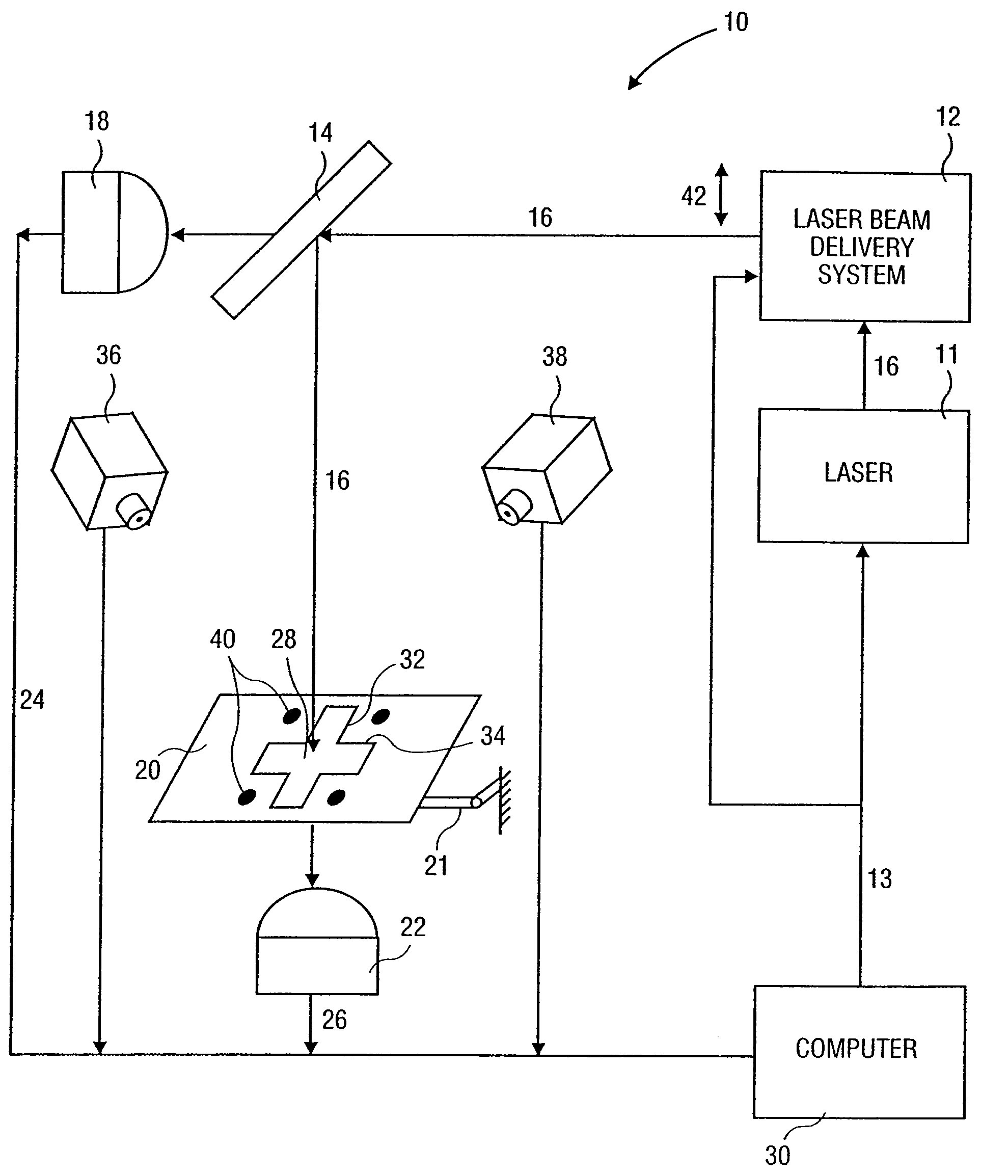
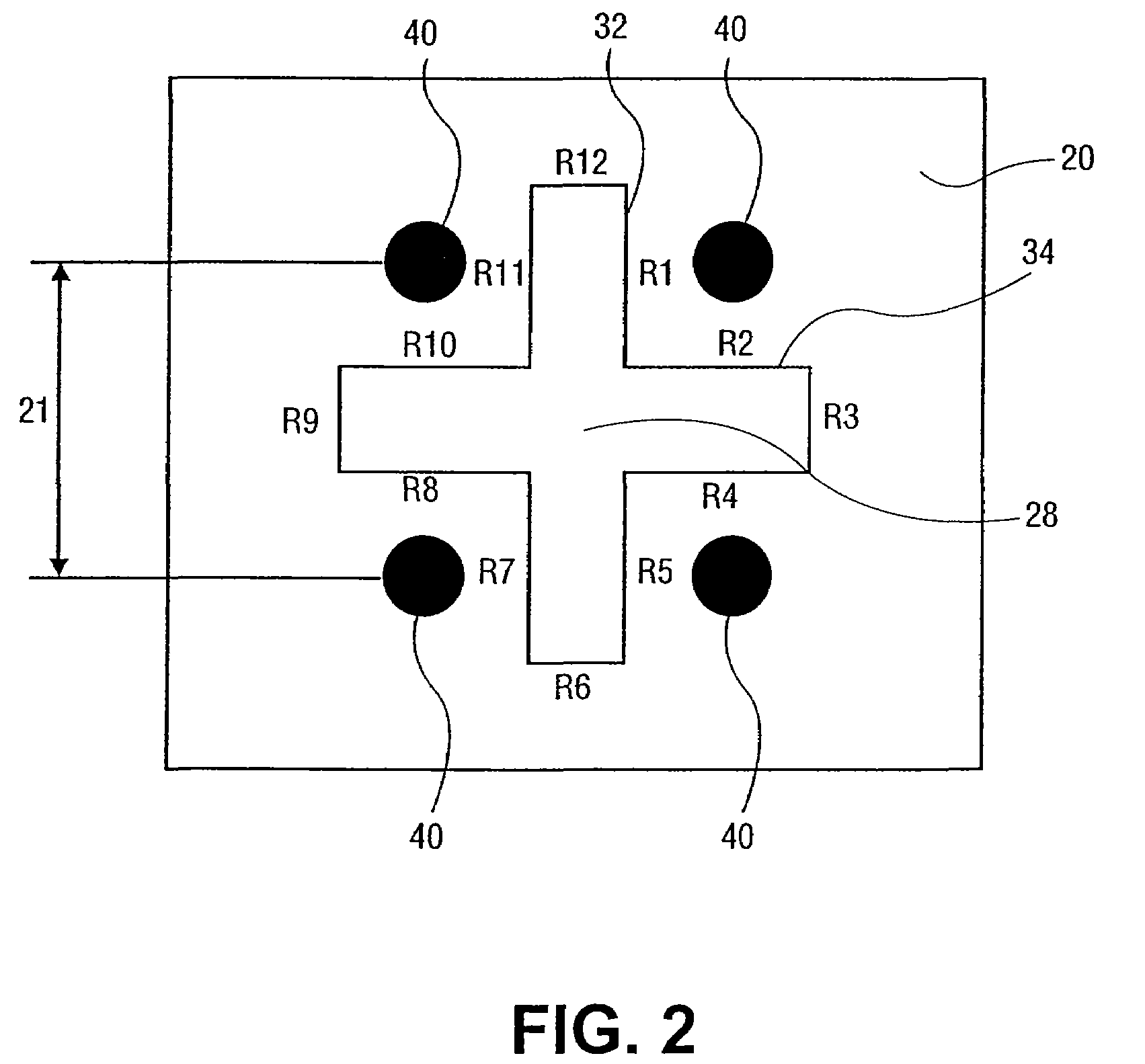
[0034]The present invention provides methods, systems, and apparatus for calibrating a laser ablation system, such as an excimer laser system for selectively ablating a cornea of a patient's eye. The present invention also facilitates aligning eye tracking cameras that measure a position of the eye during laser eye surgery. In particular, the present invention provides methods and systems which measure laser energy, laser beam shape, and / or laser beam dimensions with enhanced calibration accuracy. By determining an exact quality of a laser beam, a desired corneal ablation treatment can be accurately effected via an ablation algorithm without underablating or overablating corneal tissue, or the laser beam becoming incident on undesired locations of corneal tissue causing off-center ablations. Moreover, embodiments of the present invention allow for laser beam calibration and eye tracker camera alignment to be simply and conveniently carried out utilizing a single, reusable fixture.

[0...


PUM

PropertyMeasurementUnit
wavelengthaaaaaaaaaa
wavelengthsaaaaaaaaaa
Wavelengthsaaaaaaaaaa

Abstract

The present invention provides methods, systems, and apparatus for calibrating a laser ablation system, such as an excimer laser system for selectively ablating a cornea of a patient's eye. The invention also facilitates alignment of eye tracking cameras that measure a position of the eye during laser eye surgery. A calibration and alignment fixture for a scanning laser beam delivery system having eye tracking cameras may include a structure positionable in a treatment plane. The structure having a feature directing laser energy incident thereon to a calibration energy sensor, at least one reference-edge to determine a characteristic of the laser beam (shape, dimensions, etc.), and an artificial pupil to determine alignment of the eye tracking cameras with the laser system.

Description

CROSS-REFERENCES TO RELATED APPLICATIONS[0001]This application is a divisional of and claims the benefit of priority from U.S. patent application Ser. No. 11 / 264,785, filed Oct. 31, 2005, now U.S. Pat. No. 7,238,177, which is a divisional of U.S. patent application Ser. No. 10 / 685,253, filed Oct. 13, 2003, now U.S. Pat. No. 7,001,376, which is a divisional of U.S. patent application Ser. No. 10 / 131,622, filed Apr. 23, 2002, now U.S. Pat. No. 6,666,855, which is a continuation-in-part of U.S. patent application Ser. No. 09 / 395,809, filed Sep. 14, 1999, now U.S. Pat. No. 6,559,934, the full disclosures of which are incorporated herein by reference.BACKGROUND OF THE INVENTION[0002]The present invention is generally directed to methods, systems, and apparatus for laser calibration and eye tracker camera alignment. In particular, the present invention relates to methods and systems for measuring laser energy, shape, and dimensions of a laser beam from a laser beam delivery system, partic...

Claims


Application Information

Patent Timeline
Patent Type & Authority Patents(United States)
IPC IPC(8): G01J1/10G01B11/00A61B17/00A61F9/007A61F9/008A61F9/01B23K26/42G01B11/28G01J1/02G01J1/42H01S3/00H01S3/101
CPCA61F9/008A61F9/00802A61F9/00814B23K26/426G01J1/4257A61B2017/00725A61F2009/00846A61F2009/00855A61F2009/00872A61F2009/00897G01J2001/4261G01N21/6456B23K26/705
Inventor SOMANI, SEEMAYEE, KINGMANSHIMMICK, JOHN S.
Owner AMO MFG USA INC
Why Eureka
Try Eureka