Optical element having an anti-reflection film and optical pickup apparatus

an anti-reflection film and optical pickup technology, applied in the field of optical elements having anti-reflection films and optical pickup apparatuses, can solve the problems of worse information recording and/or reproducing accuracy, and the inability to conduct and achieve the effect of high information recording accuracy, excellent beam spot shape, and accurate recording and/or reproducing information

Inactive Publication Date: 2008-11-25
KONICA MINOLTA OPTO
View PDF8 Cites 4 Cited by
  • Summary
  • Abstract
  • Description
  • Claims
  • Application Information

AI Technical Summary

Benefits of technology

[0012]An object of the invention is to provide an optical element that can conduct accurate recording and / or reproducing for information.
[0015]In the aforesaid structure, in case that reflectance Rp1 on the optical functional surface for P polarized light of the first laser beam and reflectance Rs1 for S polarized light satisfy |Rp1−Rs1|≦2% and angle θ1 formed by the optical functional surface and the first laser beam satisfies 0°≦θ1≦60°, high accuracy of information recording and / or reproducing is conducted. Furthermore, transmittance for P polarized light and that for S polarized light gives are both high to be on the same level even on the outer circumferential portion of the optical element. Therefore, in the optical pickup device wherein a ¼ wavelength plate is arranged to be closer to a laser light source on the optical element, conversion from a linearly polarized light into a circularly polarized light and conversion from a circularly polarized light into a linearly polarized light are conducted almost surely in a total area within an effective diameter. Further, it is possible to keep a beam spot in an excellent form even in the optical pickup device wherein no ¼ wavelength plate is arranged and a linearly polarized light enters the objective lens.
[0016]Since the foregoing prevents that an amount of light entering the photodetector is reduced and distortions are generated on signals by dissociation between transmittance for P polarized light and that for S polarized light on an outer peripheral portion of the optical element, which is different from the past, it is possible to conduct accurate recording and / or reproducing of information by using the first laser beam.
[0017]Incidentally, in the optical element, it is preferable to design an antireflective film so that a phase of transmitted P polarized light and that of transmitted S polarized light may be the same. In this case, in the ¼ wavelength plate, conversion from a linearly polarized light into a circularly polarized light and conversion from a circularly polarized light into a linearly polarized light can be conducted more surely.

Problems solved by technology

Furthermore, there is a problem that deterioration of amount of light described above makes a precision of information recording and / or reproducing worse.
There are problems that the transmittance difference along the radial direction reduces the amount of incident light to the photodetector and makes a distortion of a focus servo signal, a tracking servo signal and so on, and at last the precision on information recording and / or reproducing turns worse.

Method used


Image

  • Optical element having an anti-reflection film and optical pickup apparatus
  • Optical element having an anti-reflection film and optical pickup apparatus
  • Optical element having an anti-reflection film and optical pickup apparatus

Examples


first embodiment

[0076]First, an embodiment of the optical pickup device relating to the invention will be explained.

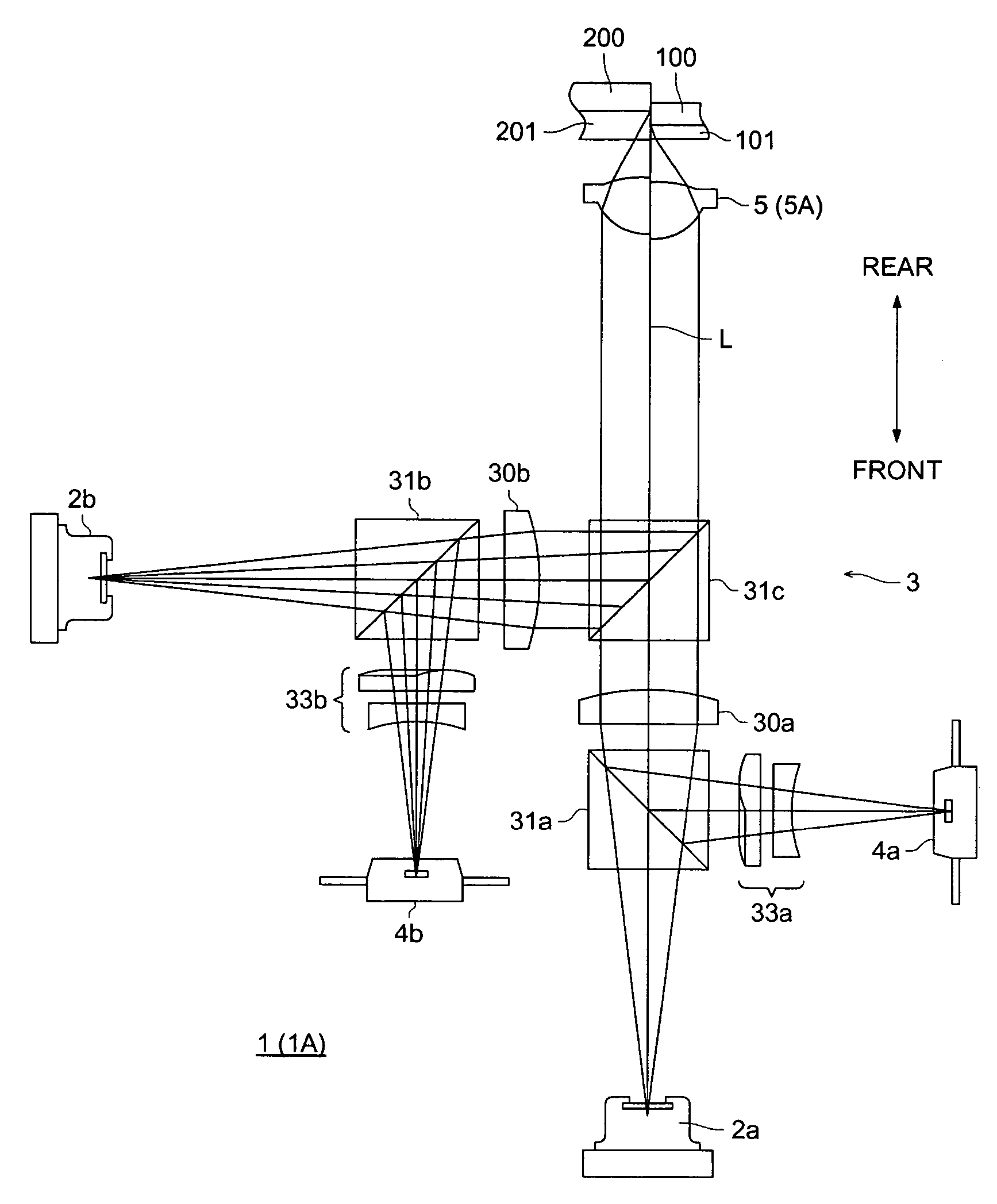
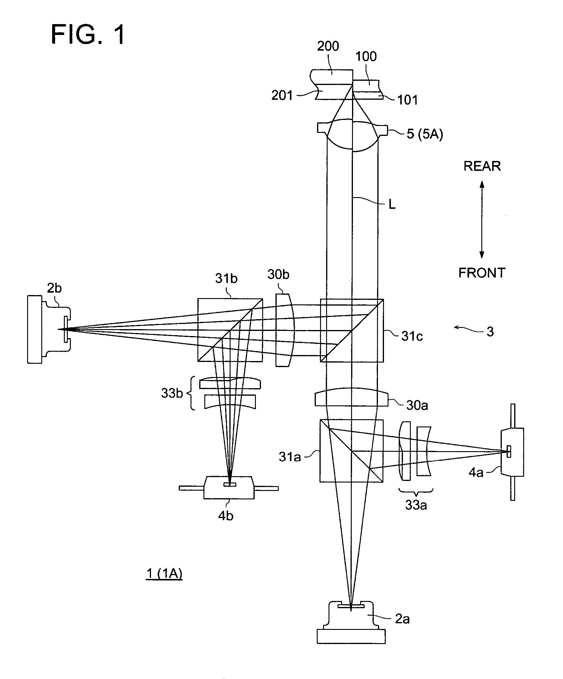
[0077]FIG. 1 is a diagram of a schematic structure of optical pickup device 1 in the First Embodiment.

[0078]As shown in the drawing, the optical pickup device 1 is provided with first laser light source 2a and second laser light source 2b both emit a laser beam.

[0079]The first laser light source 2a is one that emits a first laser beam having wavelength λ1 which satisfies 380 nm ≦λ1≦450 nm, and it is λ1=405 nm in the present embodiment. This wavelength λ1 is a working wavelength for AOD (information recording medium) 100. Incidentally, thickness t1 of protective base board 101 of AOD 100 satisfies 0.5 mm≦t1≦0.7 mm.

[0080]The second laser light source 2b is one that emits a second laser beam having wavelength λ2 which satisfies 640 nm ≦λ2≦680 nm, and it is λ2=650 nm in the present embodiment. This wavelength λ2 is a working wavelength for DVD (information recording medium) 200. Incidenta...

second embodiment

[0105]Next, a second embodiment of the optical pickup device relating to the invention will be explained. Incidentally, structural elements which are the same as those in the first embodiment are given the same symbols, and explanation for them will be omitted here.

[0106]Optical pickup device 1A in the present second embodiment is provided with objective lens 5A in place of the objective lens 5, which is different from the aforesaid optical pickup device 1.

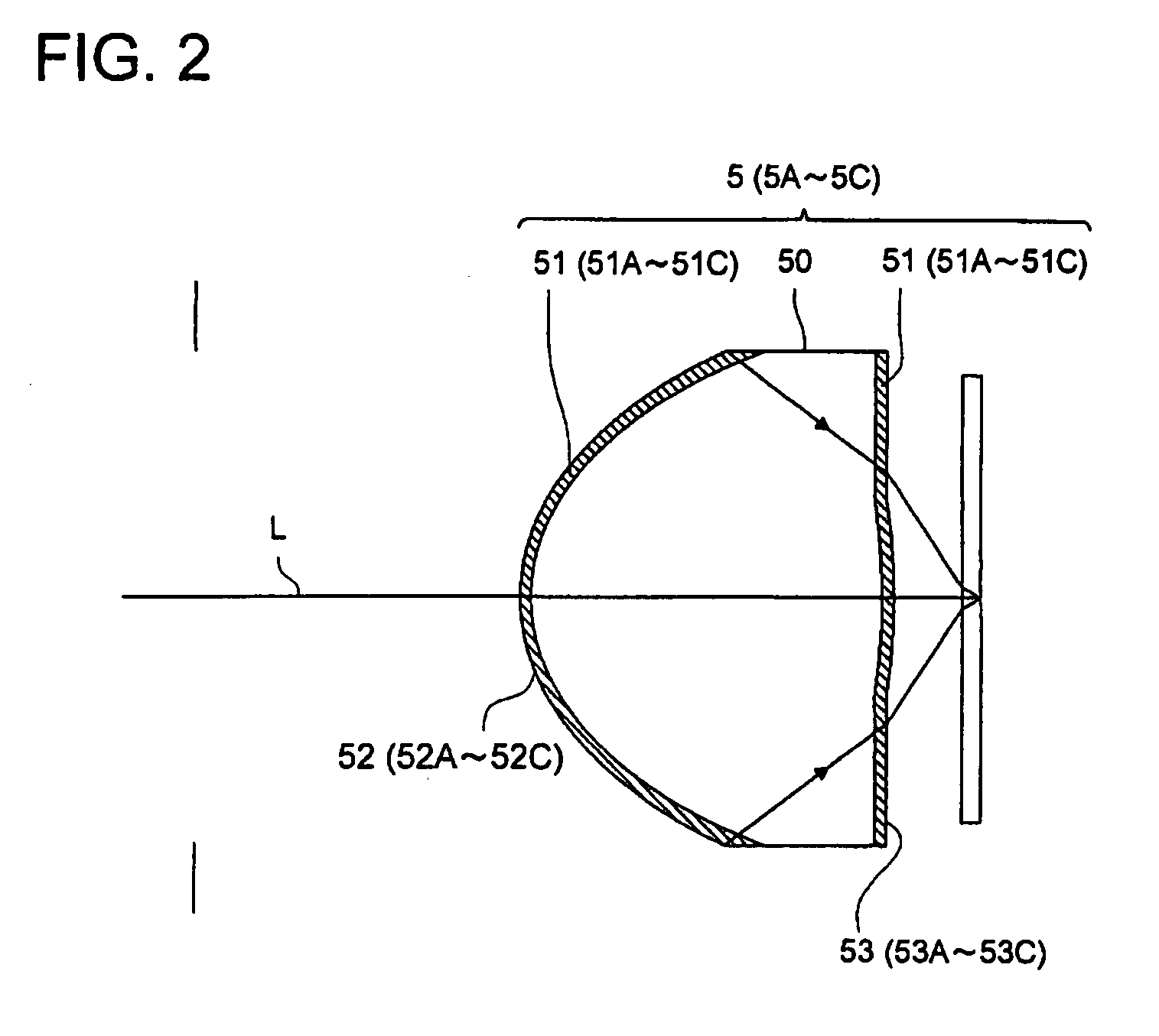
[0107]The objective lens 5A is provided with lens main body 50 and antireflective film 51A, as shown in FIG. 2.

[0108]The antireflective film 51A is provided on at least one surface of lens main body 50, and in this particular case of the present embodiment, it is provided on each of both sides of the lens main body to be optical functional surfaces .52A and 53A.

[0109]Reflectance Rp1 for P polarized light and reflectance Rs1 for S polarized light both for the first laser beam respectively on optical functional surfaces 52A and 53A ...

third embodiment

[0114]Next, a third embodiment of the optical pickup device relating to the invention will be explained. Incidentally, structural elements which are the same as those in the first embodiment are given the same symbols, and explanation for them will be omitted here.

[0115]FIG. 3 is a schematic structural diagram of optical pickup device 1B in the Third Embodiment.

[0116]As shown in this diagram, the optical pickup device 1B is further provided with third laser light source 2c, collimator lens 30c, beam splitter 31d and diffraction plate 6, and is further provided with objective lens 5B in place of the objective lens 5, which is different from the optical pickup device 1 in the First Embodiment.

[0117]The third laser light source 2c is one that emits a third laser beam having wavelength λ3 which satisfies 750 nm ≦λ3≦850 nm, and it is λ3=780 nm in the present embodiment. This wavelength λ3 is a working wavelength for CD (third information recording medium) 300. Incidentally, thickness t3 ...


PUM

PropertyMeasurementUnit
wavelength λ2aaaaaaaaaa
wavelengthaaaaaaaaaa

Abstract

An optical element to be arranged in an optical pickup apparatus for conducting information recording and / or reproducing and to converge laser light beams having a plurality of wavelengths including a wavelength of λ1 onto information recording media, includes one or more of optical element main bodies; and an antireflective film which is arranged on at least one surface on the optical element main bodies and on which an optical functional surface is formed, wherein, when the optical functional surface and a first laser beam having the wavelength λ1 makes an angle θ1 in the range of 0°≦θ1≦60°, the optical element satisfies |Rp1−Rs1|≦2% where Rp1 and Rs1 are respectively P polarized light and S polarized light reflectivities of the first laser light on the optical functional surface.

Description

BACKGROUND OF THE INVENTION[0001]The present invention relates to an optical pickup device that conducts recording and / or reproducing of information and to an optical element provided on the optical pickup device.[0002]With a tendency toward high density of an optical pickup device, a wavelength of a laser beam is becoming shorter and a numerical aperture of an optical element such as an objective lens is growing greater, in recent years. For example, in the optical pickup device employing a laser beam having a wavelength of 405 nm, a numerical aperture of an objective lens is as great as 0.6 -0.9, and a maximum angle of incidence or emergence of a laser beam for this objective lens is 60-70°, in general.[0003]Incidentally, it is necessary to keep a beam spot in an excellent form, to conduct accurate recording and reproducing for information. Then, to keep a beam spot in an excellent form, it is necessary to make the intensity of light transmitted through an outer peripheral portion...

Claims


Application Information

Patent Timeline
Patent Type & Authority Patents(United States)
IPC IPC(8): G11B7/00G02B1/10G02B1/11G02B13/00G11B7/135
CPCG11B7/1353G11B7/1374G11B7/139G11B7/13922G11B2007/0006
Inventor HIRAYAMA, HIROSHI
Owner KONICA MINOLTA OPTO
Why Eureka
Try Eureka