
Apparatus and method for electrically induced thrombosis

a technology of electrical induction and apparatus, applied in the field of apparatus and method for electrical induction thrombosis, can solve the problems of requiring a nurse to apply external pressure to the puncture site for a long period of time, causing pain, anxiety, and discomfort for patients, and causing further enlargement of the incision or puncture si

Inactive Publication Date: 2008-12-02
ABBOTT LAB INC
View PDF15 Cites 17 Cited by
  • Summary
  • Abstract
  • Description
  • Claims
  • Application Information

AI Technical Summary

Problems solved by technology

Additionally, a further enlargement of the incision or puncture will often occur as the catheter is twisted or otherwise manipulated while being advanced through the body of the patient.
Patients undergoing such procedures are often medicated with an anticoagulant such as heparin, thus requiring a nurse to apply external pressure to the puncture site for a lengthy period of time.
This procedure may immobilize the patient for an extended period of time, resulting in great inconvenience, pain, anxiety, and discomfort for the patient.
Also, additional time is required of the medical personnel and facilities.
Furthermore, the pressure application technique may fail to prevent hemorrhage and this may be life-threatening.
Moreover, a painful hematoma or bruise may develop at the puncture site because the vessel may continue to bleed internally until clotting blocks the opening in the vessel.
The treatment site closing techniques such as suturing, stapling, or gluing all require additional time to perform the procedures.
Also, these techniques introduce foreign material into the body of the patient.
Foreign material can increase the chance of infection or inflammatory response.
Relying on natural coagulation of blood to close the treatment site, however, can be time consuming and uncomfortable to the patient.

Method used


Image

  • Apparatus and method for electrically induced thrombosis
  • Apparatus and method for electrically induced thrombosis
  • Apparatus and method for electrically induced thrombosis

Examples


Embodiment Construction

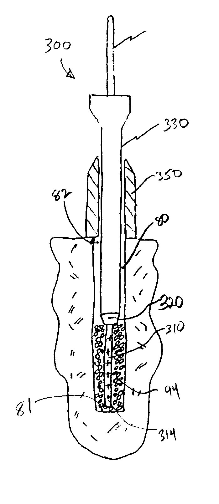
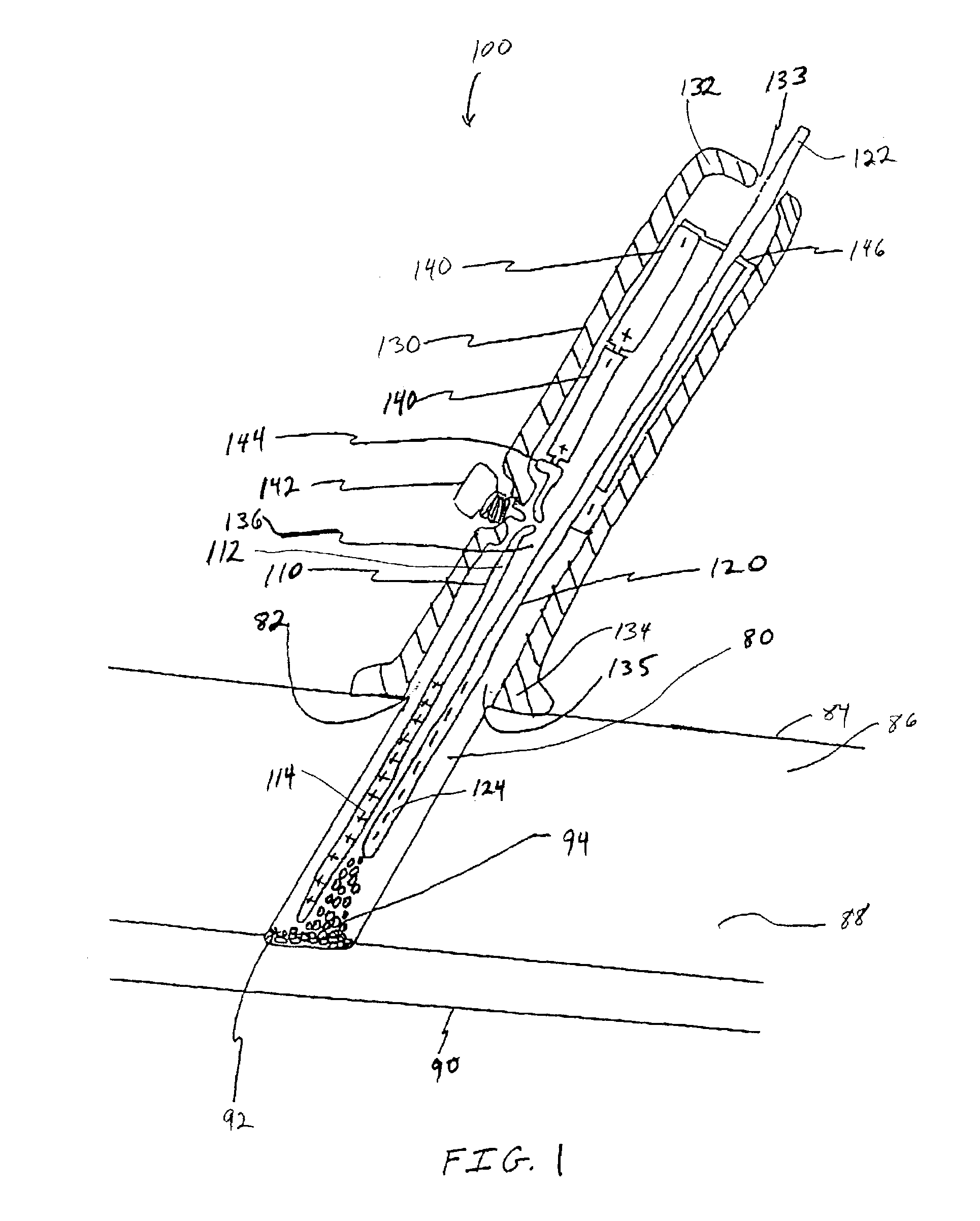
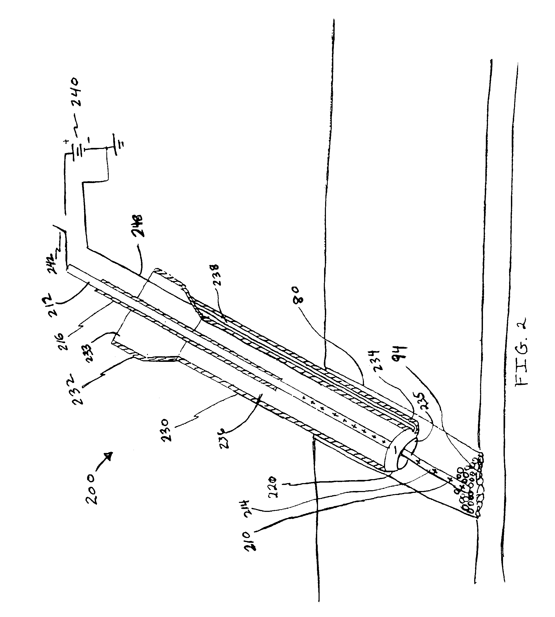
[0020]Various embodiments of a surgical device are described herein and shown in the drawings. The invention is embodied in an apparatus and method for aiding thrombosis through the application of electric potential at the treatment site of a patient. The apparatus and method can be used to repair a blood vessel, or seal a wound, opening, or puncture at the treatment site in the body of a patient. Clotting of blood (thrombosis) is induced at the treatment site by the application of a first electrode and a second electrode which cooperate to electrically induce thrombosis within the treatment site.

[0021]It has been observed that electric potential can be used to induce thrombosis. It is known that white blood cells, red blood cells, fibrinogen, and other protein components of blood are negatively charged. Natural thrombus formations within an artery may be due to abnormal electric potentials in the aortic wall. An aorta includes an outer layer of collagen and elastin that is referred...


PUM


Abstract

An apparatus and method for electrically induced thrombosis. The surgical device includes a first electrode and a second electrode. The first electrode is for placement adjacent to, near, or within a treatment site of a patient. The second electrode can be movable with respect to the first electrode. When the electrodes are charged by an electricity source, negatively charged blood components are attracted to the positively charged electrode while being repelled from the negatively charged electrode. Due to the electric potential between the adjacent electrodes, thrombosis is induced. The negatively charged blood and components form a thrombus or a clot adjacent to the positively charged electrode. The surgical device can be used to induce the otherwise natural process of thrombosis. When the surgical device is used in a treatment site such as a puncture or incision, the thrombosis can seal the opening created by the treatment site.

Description

RELATED APPLICATIONS[0001]This is a continuation of application Ser. No. 09 / 624,924, now abandoned, filed on Jul. 25, 2000.FIELD OF THE INVENTION[0002]The invention relates generally to an apparatus and method for electrically inducing thrombosis and, more particularly, to the use of electrothrombosis to aid processes including thrombosis, hemostatis, embolization, anastomotic sealing, and void filling at a treatment site of a patient.BACKGROUND OF THE INVENTION[0003]Various blood vessels and organs can be pierced or cut in connection with numerous surgical procedures or as a result of an accidental trauma. Examples of such surgical procedures include percutaneous transluminal coronary angioplasty (PTCA), angiography, biopsies, anastomosis procedures, as well as various neuro-interventional access procedures. After the surgery is complete or after accidental trauma, the treatment site, e.g., the puncture, cut, or wound, is closed. Surgical methods such as suturing, stapling, or glui...

Claims


Application Information

Patent Timeline
IPC IPC(8): A61B18/12
CPCA61B18/148A61B2017/00734A61B2018/1266
Inventor HAYASHI, REID K.LEMERE, MARK T.
Owner ABBOTT LAB INC
Learn More