Induction image heating apparatus

a heating apparatus and induction image technology, applied in the field of induction image heating apparatus, can solve the problems of increasing production cost, complicated apparatus, reducing machine productivity, etc., and reducing so as to eliminate the influence reduce the effect of leakage magnetic flux

Active Publication Date: 2008-12-09
CANON KK
View PDF20 Cites 15 Cited by
  • Summary
  • Abstract
  • Description
  • Claims
  • Application Information

AI Technical Summary

Benefits of technology

[0010]An object of the present invention is to provide a heating apparatus, of an electromagnetic induction heating type, in which leakage magnetic flux is reduced at a portion where a temperature of a heating element reaches a Curie temperature of the heating element to eliminate the influence of the leakage magnetic flux on electrical parts and the like disposed in the neighborhood of the heating element.
[0011]Another object of the present invention is to provide a heating apparatus, of an electromagnetic induction heating type, in which a thickness of a heating element is small in an area corresponding to a conveyance area, of a minimum-sized material to be conveyed and heated, which is an area in which a temperature of the heating element does not reach a Curie temperature of the heating element to reduce an amount of heat of the entire heating element, thus permitting quick start-up time of a temperature of an electromagnetic induction heating member.

Problems solved by technology

Further, as other means for preventing the temperature rise at the non-sheet passing portion, a lowering in sheet-passing speed (lowering in throughput) or abutment of heat dissipation means may be effected but is accompanied with such problems that a productivity of the machine is lowered and the addition of the heat dissipation means leads to a complicated apparatus and increase in production cost.
As a result, the resultant heating apparatus becomes a large size or is increased in complexity.

Method used


Image

  • Induction image heating apparatus
  • Induction image heating apparatus
  • Induction image heating apparatus

Examples


first embodiment

[0025]Hereinbelow, an embodiment of the present invention will be described with reference to the drawings.

(1) Embodiment of Image Forming Apparatus

[0026]FIG. 1 is a schematic structural view of an embodiment of an image forming apparatus provided, as an image heat-fixing apparatus with a heating apparatus of an electromagnetic induction heating type according to the present invention.

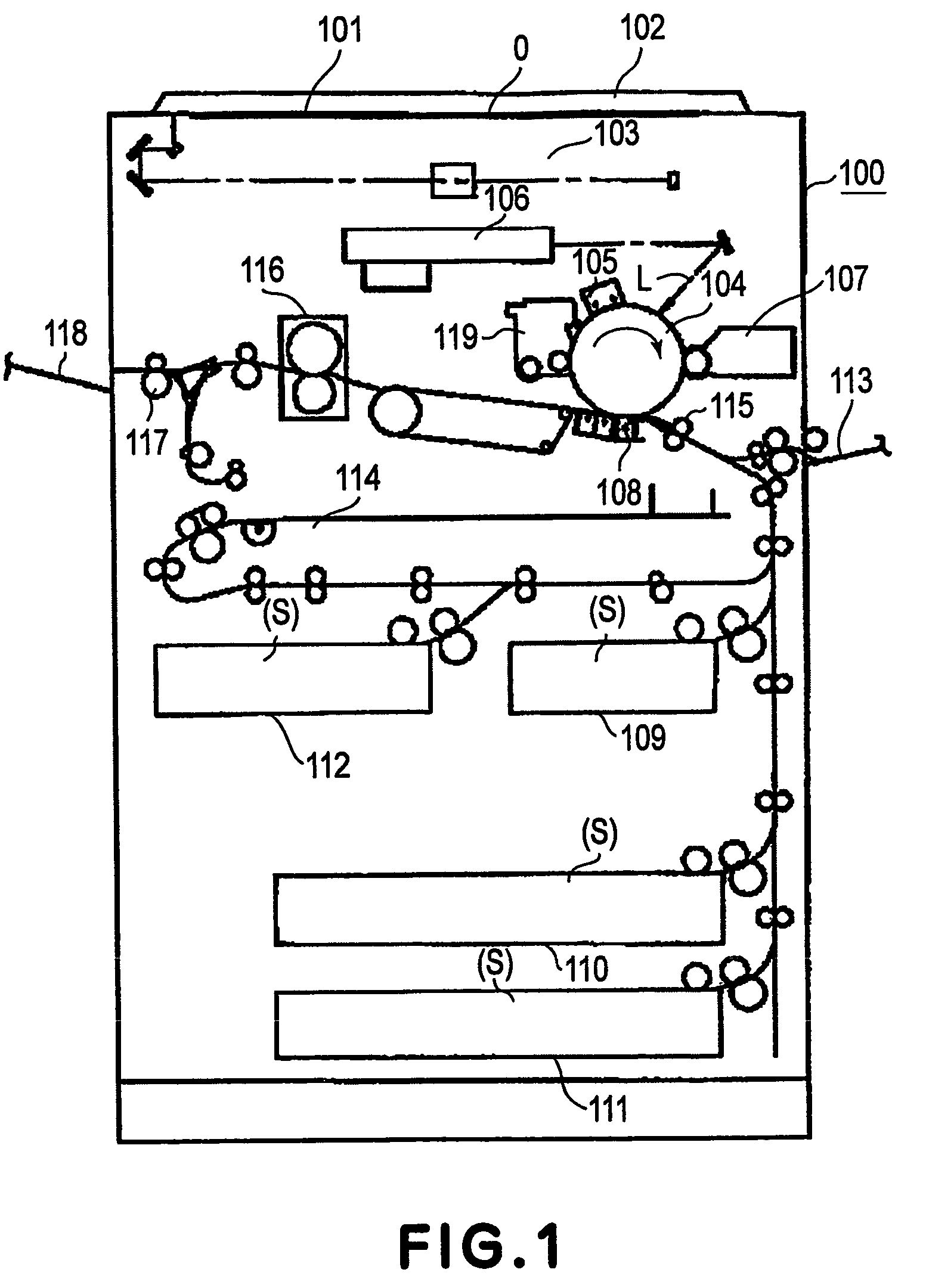
[0027]In this embodiment, an image forming apparatus 100 is a laser scanning exposure-type image forming apparatus (a copying machine, a printer, a facsimile machine, a multi-functional machine of these machines, etc.) utilizing a transfer-type electrophotographic process.

[0028]On an original supporting glass plate 101, an original O is placed face-down in accordance with a predetermined mounting standard and is covered with an original pressing late 102. When a copy start key is pressed, an image photoelectric reader (reader unit) 103 including a moving optical system is actuated to perform photoelect...

second embodiment

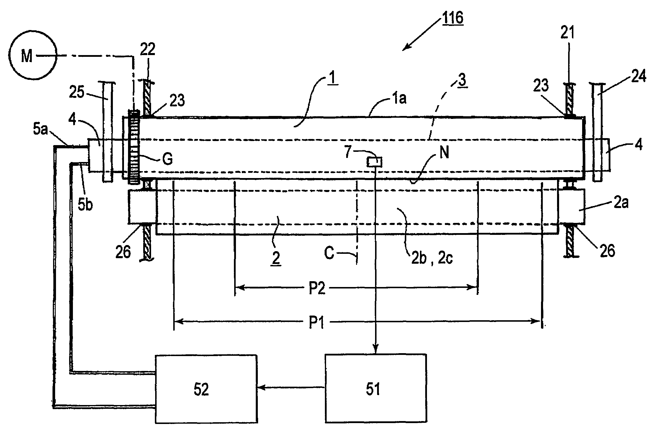
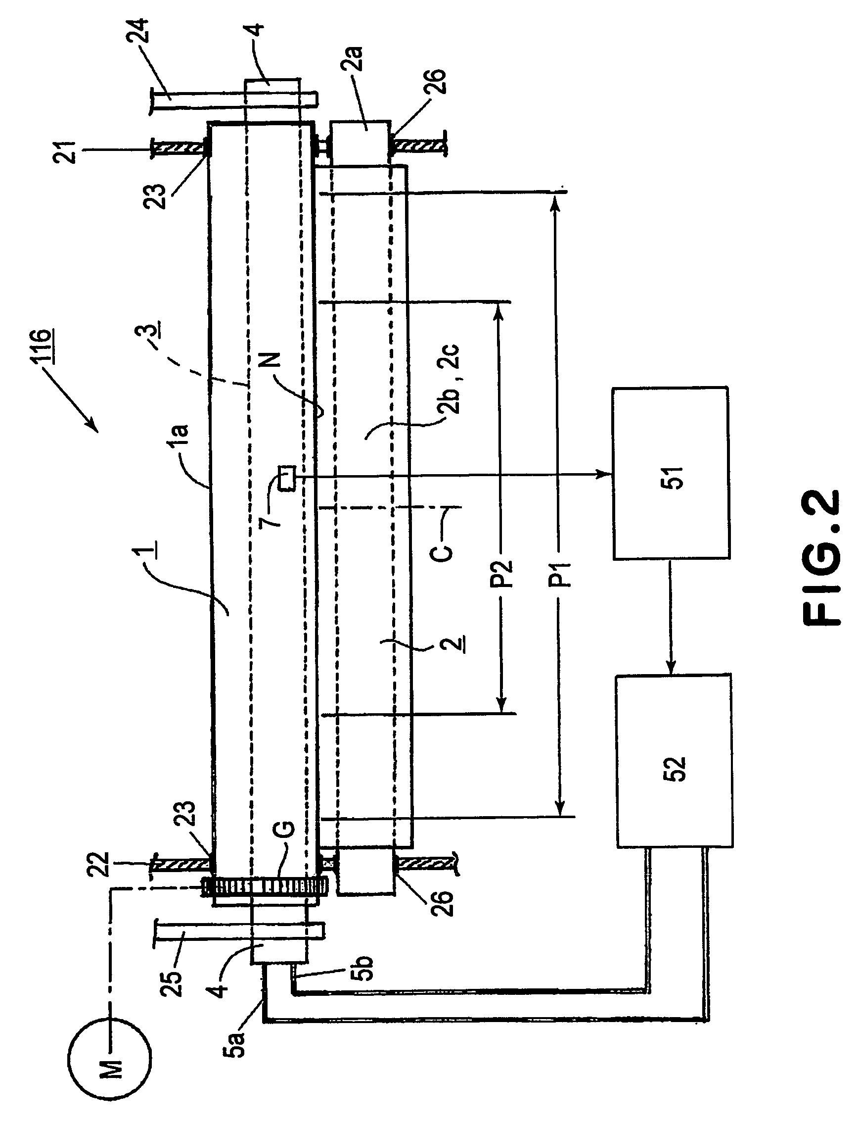
[0083]FIG. 6 is a schematic sectional view of a fixing apparatus 116 as the heating apparatus of an electromagnetic induction heating type according to the present invention.

[0084]In this embodiment, the fixing apparatus 116 has the same structure as the fixing apparatus 116 (shown in FIG. 3) used in First Embodiment except that the fixation roller 1 is changed to a flexible fixation film 1A.

[0085]As shown in FIG. 6, a film guide member 13 and an exciting coil 5 are integrally disposed as a heating assembly 3, and an endless belt-like fixation film 1A as an electromagnetic induction heating member is extended under tension around the film guide member 13, a drive roller 14, and a tension roller 15. A lower surface portion of the film guide member 13 of the heating assembly 3 and an elastic pressure roller 2 to be rotated by movement of the fixation film 1A are pressed against each other via the fixation film 1A to form a fixing nip portion N. By center reference conveyance, a record...


PUM


Abstract

In order to prevent non-sheet passing portion temperature rise occurred in a non-sheet passing area of an electromagnetic induction heating member 1, leakage of magnetic flux is reduced by setting a Curie temperature of the heating member 1 to be smaller than an acceptable upper limit temperature and setting a thickness of the heating member so that a thickness tk in a Curie temperature arrival area (P1−P2) is larger than a thickness tn in a Curie temperature non-arrival area P2 which is a conveyance area of a material to be heated having a minimum passing size.

Description

TECHNICAL FIELD [0001]The present invention relates to a heating apparatus for heating a material to be heated and conveyed by heat generation of a heating element which is induction-heated, and an image forming apparatus using the heating apparatus.BACKGROUND ART [0002]Japanese Laid-Open Patent Application (JP-A) No. Sho 59-33787 has proposed an electromagnetic induction heating type heating apparatus utilizing high-frequency induction heating as a heating source.[0003]In the heating apparatus, a coil is disposed concentrically in hollow fixation roller comprising a metal conductor (induction heating element). A high-frequency current is passed through the coil to generate a high-frequency magnetic field. The magnetic field generates an induction eddy current, whereby the fixing apparatus itself generates Joule heat due to its own skin resistance. According to the electromagnetic induction heating-type fixing apparatus, an electricity-heat conversion efficiency is significantly imp...

Claims


Application Information

Patent Timeline
Patent Type & Authority Patents(United States)
IPC IPC(8): H05B6/14G03G15/20
CPCH05B6/145G03G15/2042G03G2215/2035G03G15/2028
Inventor SHIRAKATA, JIROTAKEDA, SHOUHEIWATANABE, KOKIWAKAHARA, SHINICHIROTAKEMATSU, KOJINISHIMURA, KOICHIRO
Owner CANON KK
Why Eureka
Try Eureka