Memory device including resistance-changing function body

a technology of resistance-changing function and memory device, which is applied in the field of resistance-changing function body, can solve the problems of insufficient particle density, inability to integrate conventional single-electron transistors or single-electron memories, and inability to use coulomb blockade phenomena or the like, etc., and achieves good productivity, insufficient productivity, and memory manufacturing.

Inactive Publication Date: 2008-12-09
SHARP KK
View PDF15 Cites 37 Cited by
  • Summary
  • Abstract
  • Description
  • Claims
  • Application Information

AI Technical Summary

Benefits of technology

[0013]Another object of the present invention is to provide a resistance-changing function body manufacturing method capable of manufacturing such a resistance-changing function body with high productivity.
[0221]Moreover, the substance for forming conductive particles is implanted into the insulator by the negative ion implantation method, and therefore, the insulator and the substrate that supports the insulator can be restrained from being electrically charged during the implantation. Therefore, the implantation energy can be accurately controlled, and variations in implantation can be suppressed. Moreover, since the electric charging is suppressed, the insulator can be prevented from being destroyed by the electrical charging and from causing defects. For the above reasons, the reliability of the produced memory is improved.

Problems solved by technology

However, conventional single-electron transistors or single-electron memories are difficult to integrate because very fine processing is required to fabricate a nanosize dot capable of storing just one or several electrons and to detect a flow of several electrons.
Therefore, memory devices utilizing the Coulomb blockade phenomenon or the like lack practicability and stay at an experimental level.
With memory devices of this kind, it is often the case that the surface density of particles is insufficient or that the scale-down of the particle size is insufficient.
As a result, there are disadvantages such as narrow memory windows, larger variations and poor retention characteristics.
Also, with the method of using the fine processing technique of photolithography, etching and the like, it is extremely difficult to reduce both particle size and particle-to-particle distance to the nanometer order at the same time.
Meanwhile, there have not yet been known any resistor devices in which a multiplicity of conductive particles, which are fabricated at once, are nanometer-size particles (nanodots) superior in thermal stability.

Method used


Image

  • Memory device including resistance-changing function body
  • Memory device including resistance-changing function body
  • Memory device including resistance-changing function body

Examples


Embodiment Construction

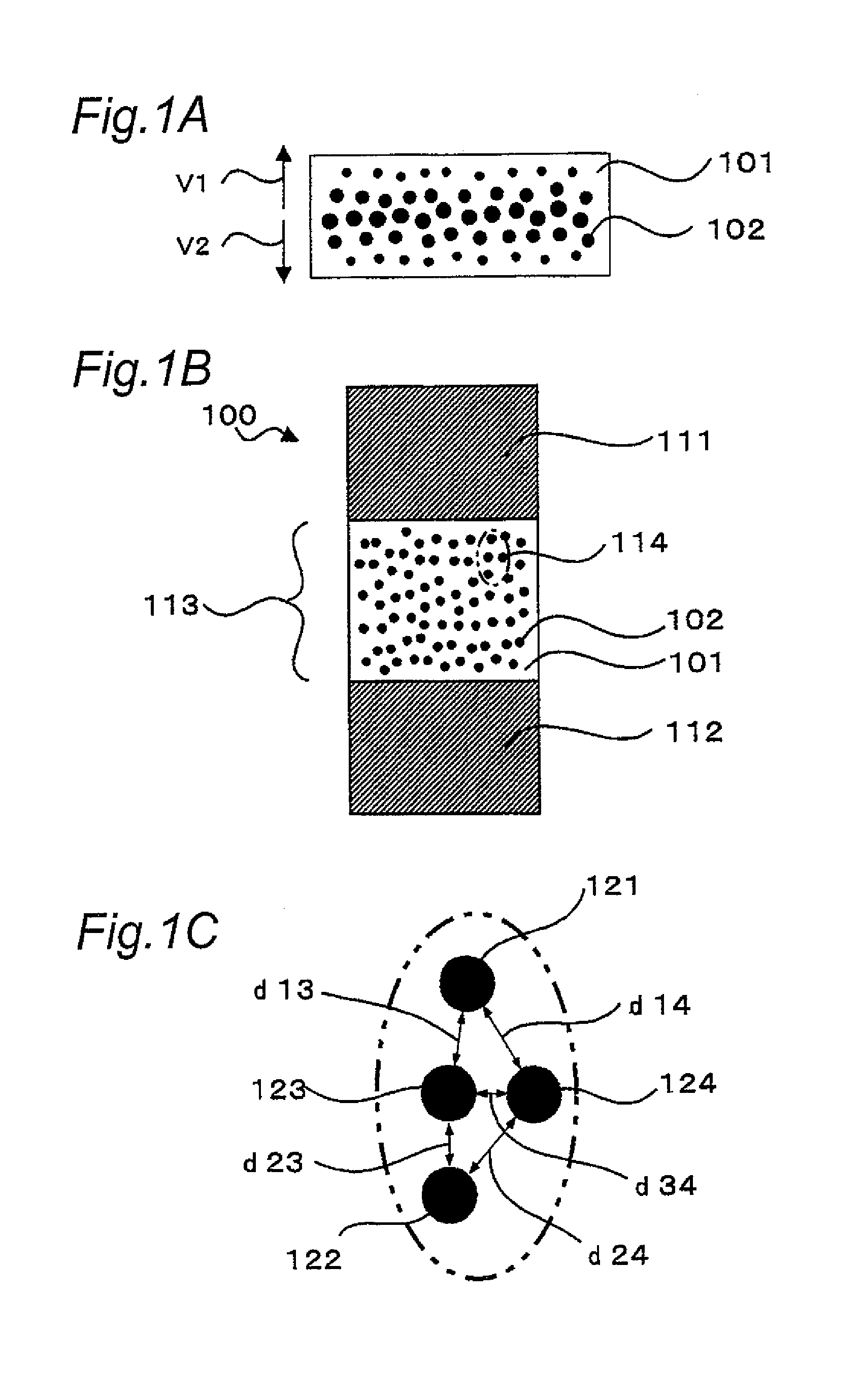
[0284]FIG. 1 shows a schematic cross-sectional structure of a resistance-changing function body of one embodiment of the present invention. This resistance-changing function body 100 includes a plurality of nanometer-size electrically conductive particles 102 which are provided in an insulator 101 sandwiched between a first electrode 111 and a second electrode so that the electrical resistance between the first and second electrodes 111, 112 changes. The insulator 101 containing the conductive particles 102 will be referred to as particle container 113.

[0285]It is noted that the resistance-changing function body according to the present invention, being usable also as a memory function body, will also be referred to as memory function body from time to time.

[0286]The resistance-changing function body 100 is fabricated in the following manner according to processes shown in FIG. 3 (FIGS. 3A to 3D associated with one another will be referred to generically as FIG. 3, so is the case al...


PUM


Abstract

A resistance-changing function body includes an object made of a first substance and interposed between a first electrode and a second electrode, and a plurality of particles made of a second substance and arranged within the object so that an electrical resistance between the first electrode and the second electrode is changed before and after application of a specified voltage to between the first electrode and the second electrode. The first substance makes an electrical barrier against the second substance. With this constitution, by applying a specified voltage to between the first electrode and the second electrode, the electrical resistance can be changed depending on a state of the particles made of the second substance. Also, by virtue of a simple structure, a resistance-changing function body of small size is provided with low cost.

Description

TECHNICAL FIELD[0001]The present invention relates to a resistance-changing function body including a plurality of fine particles and a manufacturing method therefor. The invention also relates to memories, circuits and electronic equipment having such a resistance-changing function body.[0002]It is noted that the terms “resistance-changing function body” refer to a device or element that changes in electrical resistance after application of a voltage. Typically, the resistance-changing function body has a plurality of electrically conductive fine particles contained in a dielectric. Since such a resistance-changing function body is capable of being operated as a memory function body having a memory effect, the terms “resistance-changing function body” and the terms “memory function body” will be used herein as appropriate, where the former is a concept containing the latter unless the case is apparently different in the following description.BACKGROUND ART[0003]In recent years, wit...

Claims


Application Information

Patent Timeline
Patent Type & Authority Patents(United States)
IPC IPC(8): H01L29/02H01L27/24H01L29/861H01L45/00
CPCH01L29/8615H01L45/10H01L45/1206H01L45/1226H01L45/14H01L45/1608H01L27/2409H01L27/2436H01L27/2481H01L45/1233G11C13/0004Y10S438/90H10B63/84H10B63/20H10B63/30H10N70/25H10N70/253H10N70/823H10N70/881H10N70/826H10N70/021
Inventor ARAI, NOBUTOSHIIWATA, HIROSHIKAKIMOTO, SEIZO
Owner SHARP KK
Why Eureka
Try Eureka