Electric wheel
a technology of electric wheels and rotating wheels, which is applied in the direction of magnetic circuit rotating parts, magnetic circuit shape/form/construction, cycle equipments, etc., can solve the problems of reducing the output power of the wheel-in motor, reducing the production efficiency of the wheel suspension system, and reducing the production efficiency of the wheel-in motor. , to achieve the effect of reducing the radial thickness of the rotor of the wheel-in motor, reducing the diameter of the electric gap,
- Summary
- Abstract
- Description
- Claims
- Application Information
AI Technical Summary
Benefits of technology
Problems solved by technology
Method used
Image
Examples
second embodiment
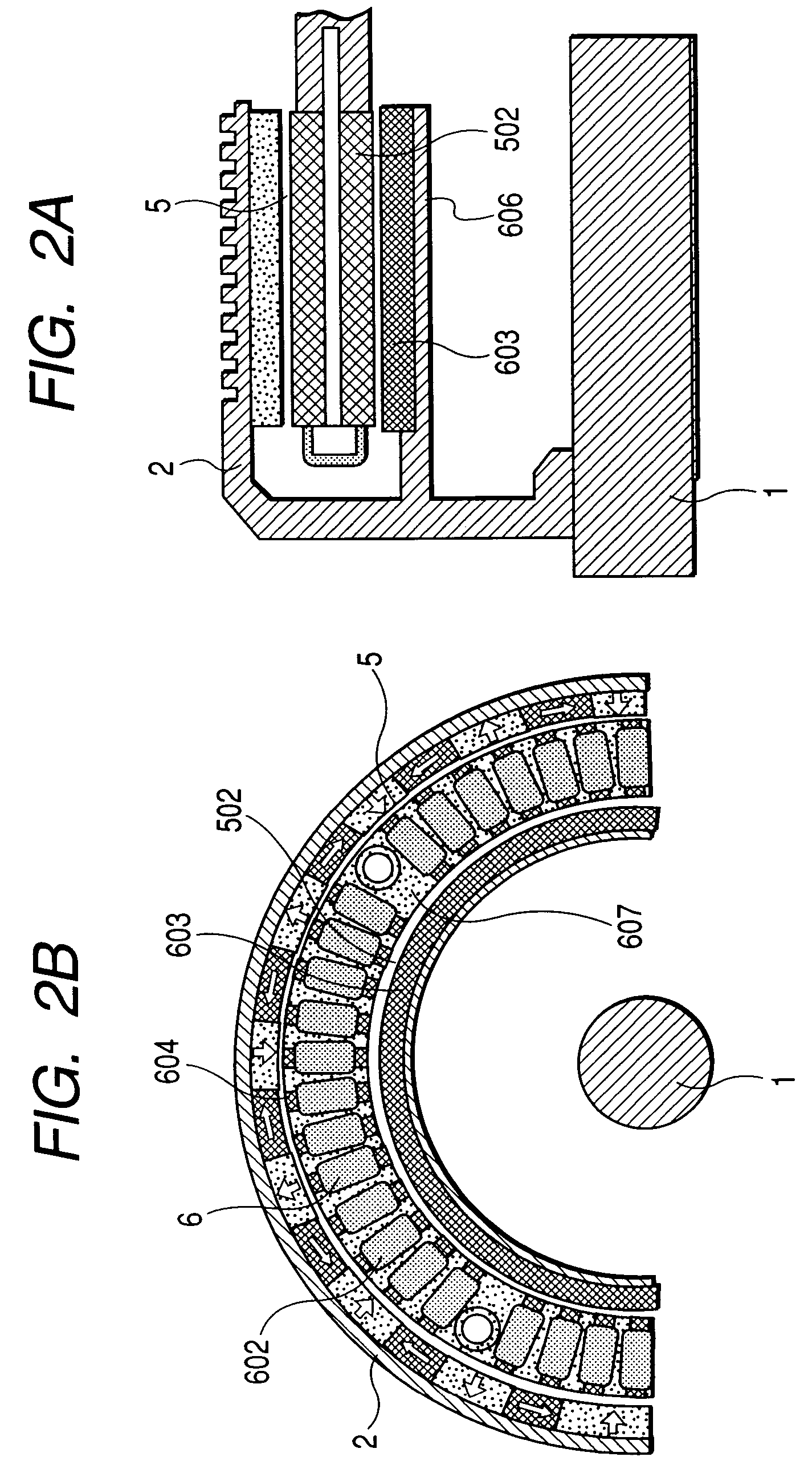
[0041]FIG. 2A is an axial half sectional view of an outer-rotor type wheel-in motor for use in an electric wheel according to a second embodiment of the invention. FIG. 2B is a half front view of this wheel-in motor when viewed from the right side in FIG. 2A.
[0042]In the second embodiment, unlike the first embodiment, the back core part 603 and the tooth pieces 604 are separated from each other, and the back core part 603 is provided on the rotor 4 side such that it faces the electric gap 502. More specifically, an annular part 606 extending in the axial direction is provided in the disk part of the bowl-shape member 2, and the back core part 603 is fixed to the annular part 606.
[0043]In the second embodiment, the tooth pieces 604 and the coils of the three-phase winding 602 of the armature 6 are bonded by an adhesive support 607 having good heat-conductivity to form the armature 6 in the shape of a cylinder. The coils of the three-phase winding can be wound around each of the tooth...
third embodiment
[0045]FIG. 3A is an axial half sectional view of an outer-rotor type wheel-in motor for use in an electric wheel according to a third embodiment of the invention. FIG. 3B is a half front view of this wheel-in motor when viewed from the right side in FIG. 3A.
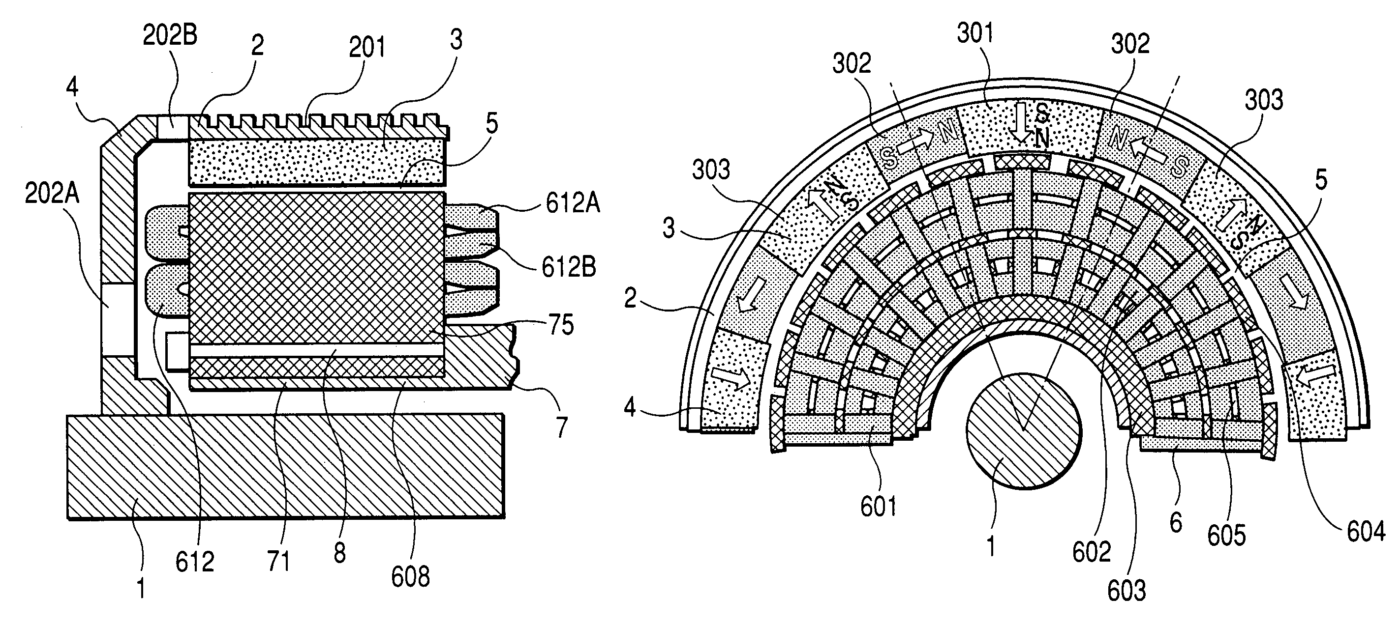
[0046]The third embodiment is different from the second embodiment in that the back core part 603 is replaced by a magnet-type field generator 2b in the shape of a cylinder constituted by magnets arranged in the Halbach array. The magnet-type field generator 2b is fixed to an annular part 608 similar to the annular part 606 explained in the second embodiment. Since the magnet-type field generator 2b is applied with centrifugal force, the magnet type field generator 2b is covered by a ring member made of non-magnetic or magnetically saturated material for the purpose of mechanical protection. Radiating fins similar to the radiating fins 201 explained in the first embodiment are provided in the inner surface of the annular part 608...
PUM
 Abstract
Description
Claims
Application Information
 - R&D
- Intellectual Property
- Life Sciences
- Materials
- Tech Scout
- Unparalleled Data Quality
- Higher Quality Content
- 60% Fewer Hallucinations
Browse by: Latest US Patents, China's latest patents, Technical Efficacy Thesaurus, Application Domain, Technology Topic, Popular Technical Reports.
© 2025 PatSnap. All rights reserved.Legal|Privacy policy|Modern Slavery Act Transparency Statement|Sitemap|About US| Contact US: help@patsnap.com


